Audio ADC

cfogarty

New Member
I am attempting to create servo movement based on the sound level at an ADC. I am currently using my computer’s 1/8” audio out. I am getting pretty decent results in the 0-30 range. I would like better resolution.

I built a simple LM386 circuit with the stock 20x gain. This caused my debug window to disappear from time to time. I am guessing it was too much amplification.

I read through the forums and found lots of great op-amp information but even with some modifications to my circuit to include a 10k pot for input volume control I was getting poor results and when an 8ohm speaker was connected I was hearing loads of noise!

As a side note… I have also been working on using electret microphones and LM741/LM386 preamp’d and non preamp’d with little success.

Does anyone have a tested, working circuit?

I even went so far as to buy breakout boards from Spark Fun. They don’t work the way I expected and Spark Fun seems to think it is a problem with the A2D converters and that I should use the chip they used for testing.

Any help would be great!

Thanks!

Corey
 
Last edited:

Michael 2727

Senior Member
Because of the nature of sound WAVES, even loud sounds have a zero or low voltage
content from the op amp output. Try feeding the output into a small capacitor
100n, 0.10µF to 1 µF (between output & NEG) then feed that to your ADC input.
This will add a momentary Hold function to the output voltage.
You should include a resistor to NEG to discharge the capacitor (try 2K to 10K)
or the voltage may stay high for too long, experiment.
You could also include a diode before the capacitor to stop charge from the
capacitor feeding back to the op amp. NOTE: This will block very low level sounds
due to the 0.6V diode forward voltage drop.

Edit: Welcome to the forum BTW and you have posted into the
"Finished Projects" section of the forum, the thread may get shifted
into the "Main" forum if someone can be bothered.
 
Last edited:

cfogarty

New Member
A Little More Luck Today

I tried playing with the circuit a bit. I have always been afraid to try variations on book examples for fear of frying something. But I figured how bad can it be...;-)

Here was the original:


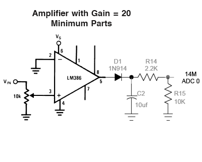
Here is what seems to be working:


So I guess my question would be... Is this okay, if not, why?
 

BeanieBots

Moderator
Not quite.
That will amplify an input but to detect audio LEVEL, you need a detector.
If you have a look at diagram in the link I posted, you will see a diode feeding an RC just before the final transistor. That is the detector.
If you increase your output cap to at least 10uF and then feed it into a similar detector circuit (no need for the tranny), it might work.
You mentioned electet microphone. I don't know about them but I believe they require a DC bias to work correctly. Hence, I don't think your cicuit would be suitable for that type of microphone. I might be wrong!
 

cfogarty

New Member
Isn't the ADC a detector or am I confusing two different things?

Maybe the code will help...

There are 5 LEDs and a Servo connected to the six outputs.

audio:

readadc 0, w1
'debug w1

readadc 4, w2
'debug w2

if w1 > 20 then
high 0
servo 5, 200
else
low 0
servo 5, 205 'servo at zero (no sound)
end if

if w1 > 50 then
high 1
servo 5, 180
else
low 1
end if

if w1 > 100 then
high 2
servo 5, 140
else
low 2
end if

if w1 > 150 then
high 3
servo 5, 110
else
low 3
end if

if w1 > 200 then
high 4
servo 5, 80 'servo at max (lots of sound)
else
low 4
end if

pause 30

goto audio
I find the debug can't keep up with the changes in the audio but I am not overly concerned about watching the status on screen.
 
Last edited:

cfogarty

New Member
I suppose I should have kept the two issues separate. I was thinking it might be a general amplifier issue.

About two months ago I decided to add ears to one of my mobile robots. I started with Radio Shack Electret microphones and a circuit from the Op-Amps project guide. I was never able to get a good quality sound level to feed to an A2D converter. I am using NXP I2C A2D converters on that project. (I am using a volt meter set to DC to watch for sound levels. I also tried the AC setting since sound is not a constant.)

About three weeks ago I found a Halloween project that looked exciting:

http://www.scary-terry.com/audioservo/audioservo.htm

I figured I could use a PICAXE to do the job. Terry’s design is based on sending the servo to its extreme ends based on the sound reaching a set level. It doesn’t care if the sound is quiet or loud, it just has to make it over a threshold. I wanted to refine the idea a bit and make the servo position based on sound level.

I purchased an 1/8” stereo phone jack and wired the Left and Right tracks to the two A2D converters on the PICAXE 14M. I patched a cable between my computer’s audio out to the newly wired phone jack.

Then I built the readadc program to read the two A2D’s and debug the output. The output ranged from 0-30. I wanted more range. It would be nice to track a quiet voice and move the servo just a little.

Enter LM386 to the party.

I can try a diode -> R/C setup, if there is a negative in using the circuit above… can I assume I need D1, C4 and R8? And if so can I swap D1 for a 1N4001? I have a bunch of them laying around.
 

BeanieBots

Moderator
It should work if you make your amp feed into a circuit like his does. That is, the bit between his amp and the 4066.

The theory:-
Put simply, a loud speaker movement matches the voltage applied to it. An indication of the loudness cannot be determined by taking a very fast picture and looking to see where the cone is. You need to know the furthest distance the cone has moved. That's what the detector part does. The diode charges the cap very quickly via the diode. Hence, the cap will be at whatever the PEAK voltage was at. A resistor then slowly discharges it. This gives time for the A2D to read the voltage. (the PEAK voltage). Without that circuit, you just get a "snapshot" of what the drive voltage was at the time you took a reading. That could be anything between nothing and maximum. Not much use really!

Hope that makes sense.
 
Last edited:

cfogarty

New Member
Based on the diagram you had sent:

http://www.rev-ed.co.uk/docs/picaxe_sound.pdf

In Stage 4 - Buffer and Time Delay I figured the idea was to hold the peak value for a time. I am starting to see what the concern is. I noticed with my current working environment that the voice track had to be pretty slow and use long pauses between sounds to get a good visual look. (Servo movement was sporadic at best when the voice track was normal conversational talking or song singing.)

So my revised circuit should look like this:


Is it okay to swap out D1 (1N914) in this revised circuit for a 1N4001? It looks like the difference is only Voltage and Current Rating according to DigiKey…
 

BeanieBots

Moderator
The overall principal of your latest circuit should work.
The diode is not critical so a 1N4001 will be fine.
I don't know anything about your source, so I cannot comment on the amplifier stage.
The RC looks a bit too quick to me. 10uF//12k2 is quite a short time constant and I doubt your servos will be able to keep up. You will need to experiment to get the optimum values.
If I was in your position (presumably without a 'scope), I'd make C2 bigger, maybe even 100uF and make R15 a 100k POT. I'd also put 100nF direct on the ADC pin.
Again, not knowing anything about the source, R14=2k2 is a good place to start.
If you don't have a 'scope, try to borrow one. It will save a lot of experimentation and frustration.
 
Top