Analog to Digial - Adjustable Bench Power Supply

Mad Professor

Senior Member
Analog to Digital - Adjustable Bench Power Supply

Good Day All.

I have been keeping a eye on the "picaxe controlled variable power supply" topic, but mine is not quite the same so I have started this one.

I own a Watson W-10AM Bench Power Supply Unit, 0-15v @ 10amps.

The voltage is adjusted by a pot on the front, The pot does make it quite hard to get the voltage where I want at times.

So I would like to remove the pot, and fit four buttons, two to adjust the voltage up / down by 1.00v, and the other two buttons to adjust the voltage up / down by 0.05v.

Here are some pictures of the unit.
http://www.mad-professor.co.uk/Misc/W-10AM/Watson W-10AM (1).jpg
http://www.mad-professor.co.uk/Misc/W-10AM/Watson W-10AM (2).jpg
http://www.mad-professor.co.uk/Misc/W-10AM/Watson W-10AM (3).jpg
http://www.mad-professor.co.uk/Misc/W-10AM/Watson W-10AM (4).jpg
http://www.mad-professor.co.uk/Misc/W-10AM/Watson W-10AM (5).jpg

Heres a few datasheets.
C1815 Datasheet
KBPC2502 Datasheet
LM324N Datasheet


Will a PicAxe be able to do what I am after?

Thanks for your time.
 
Last edited:

Andrew Cowan

Senior Member
Not sure how a picaxe could do it, but I had the same problem with a 10V power supply (not sensitive enough). I replaced the 10K pot with a 10 turn, 10K pot, thus meaning for me, 1 turn = 1V. It is easily sensitive enough to set it to a 100th of a volt.

Andrew
 

BCJKiwi

Senior Member
Also have bench power supply with the same issue.
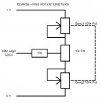
Had thought about simply adding a second pot at the end of the first one with an order of magnitude (or two) difference so one was coarse, the other fine.
Have not yet pulled it apart to see exactly how the pots are set up so not sure how practical it would be.
Concentric shaft pots would make mounting easier, and there is always the multiturn pot approach.

Argh! The dreaded cross posting.
 

MFB

Senior Member
Digital potentiometers

You could try replacing the voltage adjustment with a digital potentiometer. Some of these can be controlled by simply toggling switches, whilst other need to be driven from an I2C or SPI bus. Maxim produces a wide range of digital potentiometers, some with 1024 steps.
 

wapo54001

Senior Member
If double the resolution would be enough, you could add a resistor on both sides of the pot with a dpdt switch that always shorts one or the other so that the full pot travel actually controls only half the available range at any given time, with the switch determining whether it's the top half or bottom half of the range.
 
Last edited:

wapo54001

Senior Member
If you go to more precision on the control, will you be replacing the analog meters with more accurate digital meters?
 

BCJKiwi

Senior Member
If I understand the First posted pic correctly, Current Pot is on the left, Voltage on the right.

Adjustability and 'feel' would be improved by fitting a much larger diameter knob on the Voltage control - if the diameter is doubled the hand moves twice as far at the circumference for the the same angle of rotation - just makes it easier to handle! Also , if the pot is very free running, adding a small amount of friction on the spindle helps to obtain fine increments.

See also the double gang and divider pot approach in the 08M adjustable power supply thread - pic attached. This is the same principle as Wapo applies in thread #5
 

Attachments

Last edited:

Dippy

Moderator
Whilst I appreciate the benefits of a larger knob, the common method is a multi-turn pot.

I have - and still use - an ancient Bench power supply donated by the Admiralty. Vintage 60s or 70s. It started playing up recenlly so I sprayed a bit of 'switch contact cleaner' on the pot windings. Good as new.

If I were to design a bench power supply I would simply have a numeric keypad and tap in the required voltage and current limit. Maybe also have a fine-tune knob.

But what has been shown here is the potential to make a reasonable power supply at low cost. Would it be good enough as a pukka bench power supply? ... not sure. I'd have tried the LED/LDR optocoupler plus PWM personally.
 

BCJKiwi

Senior Member
Agreed, multiturn pots are relatively expensive - at least they are here. If you've got plenty of money to spare, RS have some very nifty push button and multiturn knobs to fit on your exisitng pot with a digital readout - only cost NZ$80 plus!
Thought the push buttonn and electronics might be a bit overkill for upgrading the existing unit if a simpler approach would so the job.

Then there are the digital pots that accept PB input, Dallas 1669 and 1869 for example. They handle all the up and down key press, debounce, repeat etc - only 64 position though.

It's interesting that there is a large diameter knob on the left and a small diameter knob on the right.
 
Last edited:

Dippy

Moderator
Sorry, some of my comments were referring to the other thread... brain muddle.

I'd just do what Andrew suggests and get a quality multi-turn pot.
Unless you have a circuit diagram or understand the circuit absolutely you can't merely replace the pot willy-nilly with a digital pot, or opto-coupler or MOSFET. The ratings e.g. voltages and currents required may all be wrong.

"It's interesting that there is a large diameter knob on the left and a small diameter knob on the right. "
- is it? You ought to get out more ;)
No, but seriously, I would have guessed a bigger knob is simply for greater precision of setting. Unless there is something else there which we can't see on the piccy.

My PSUs use multiturn pots and the control is very easy. And I only have small knob.
Whilst upgrading to push button sounds good, I doubt that you'll do it. Just spend a few quid on a GOOD multiturn pot and be done with it. Check size first though.

But as it uses cardboard pcbs with upright mounted resistors then I'd throw it away and buy a Thurlby Thandar :)
 

BCJKiwi

Senior Member
"No, but seriously, I would have guessed a bigger knob is simply for greater precision of setting"

My point exactly!
 

BCJKiwi

Senior Member
Well we are back to where we were - replace the small knob with a big knob and see how it goes - looks like you'd probably have room for one about 3X the diameter - that should produce a noticeable improvement.

How about it Prof? - we've not heard from you for a while.
 

Mad Professor

Senior Member
Sorry guys i've been away trying to convert a Rover Mini SPi from MEMS ecu to a MegaSquirt, been having a few problems so not had much time to pop on here unto now.

As a few of you have said fitting a bigger dia knob will help with the fine adjustments, witch I will probley do for the short time.

In an ideal world I would like to move the control over to digital like in my 1st post.

I am going to be replaing the guages on the front with digital ones, I did buy some to replace them with, but ended up being to big to fit, and I did not really want to cut the unit up to much.
 

wapo54001

Senior Member
Check the Lascar website. They are an English company, I believe, and they have very nice small meters -- .8"H x 1.4"W that mount with a single 1/4" hole rather than a rectangular cutout.
 
Top