Fitfurnowt
New Member
Hi everyone,
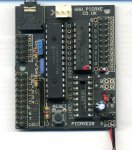
These questions (3) relate specifically to the PICAXE-28X1 Project Board, using it to drive motors and solenoids and suitable power supplies.
I've only recently become aware of what a microcontroller is, what it can do, and PICAXE. My electrical experience goes no further than having rewired my house, soldered wires for various connectors ect. I have picked up a bit about volts, amps and the like and understand what resistors and capacitors do, but I don't yet go much beyond that. So my questions come from that knowledge.
I want to build a system that that is initiated by a switch and will control two motors (forward only, not reverse) and a solenoid valve rated at 12volts, 0.6 amp. Once I've learnt how to do that, I intend to add a second switch to control a second solenoid, and as my knowledge increases, an LCD display.
Having read up through the manuals, and PICAXE web site, I got all excited and got a PICAXE-28X1 starter pack. It includes the ULN2803A chip with the Darlington drivers on each of the eight digital outputs. The literature say's that the outputs will each drive up to 800ma and that I can use a second 12v power source to drive the ULN2803A and it's outputs.
Will the ULN2803A drive up to 800ma in total across the 8 outputs, with up to 800ma on any one, or does this mean that it will drive 800ma on each output independently, making 6.4 amps in total? I got the PICAXE Microcontroller book with my order but it doesn’t cover the newer X1 chips.
Also, am I correct in thinking that I simply connect the solenoid and motors to the ULN2803A with no other components?
I've not got the motors yet (I thought I'd get 12volt to keep things simple) so don't know what current they will need (they are used for small dosing pumps), but assuming they require the same as the solenoid, that would mean a current requirement of 1.8 amps for my initial system.
The last question is about the power supply. Is a computer power supply a suitable option? I understand they supply 12 volts at a high wattage which (if the above is correct) would supply enough power.
I'm sure these will seem like bone questions to you guy's so I apologise for my ignorance. I can't seem to find an answer in any of the documents on the site or forum.
")