433MHz transmitter interference with stripboard?

moxhamj

New Member
Problems? Probably not. In fact, it may even help, if you have the antenna mounted perpendicular to the stripboard and the stripboard is earthed, you could end up with a groundplane. But it will depend on the distances and the multiple of wavelengths. Ideally, get the antenna in free air and no metal between the antenna and the receiver, and overrate the power a bit so the signal definitely gets there. Metal parallel to an antenna and within 1 wavelength is not so good. Your setup looks fine.
 

westaust55

Moderator
433MHz transmitter

Thanks,

See the coiled antenna on the opposite side of the box, near the battery compartment
As Dr-Acula has stated,
The idea with a helical antenna is to have the antenna vertical.

Better might be to have it above your circuit board or
an alternative mount some metal on the inside of the box lid and connect it to 0V with the antenna external and vertical.
This metal acts like a ground plane and inproves the antenna performance.

Do a google search for "antenna" and "ground plane"
 

Dippy

Moderator
WRT mounting the "transmitter" etc..

Are you talking about the transmitter MODULE or the ANTENNA?

Some old/cheap/unscreened modules can be detuned by unsuitable positioning.

Some sensitive circuits could be upset by RF - so that depends on your circuit.
A definitive answer isn't possible without more details (and sometimes its suck-it-and-see). String of long piece a how is.

You should read the transmitter Manufacturer's DATA SHEET.

Most reputable manufacturers can provide info on screening/mounting of the module AND ALSO tips on mountng the antenna.
If it's not mentioned in the manual you can, with proper manufacturers, actually phone them up and speak to an EXPERT on that particular product.
I guess it depends where you got the module and what make it is.
 

manuka

Senior Member
Ground plane issues & matching etc aside, I've certainly experienced numerous RF breakthru' hassles over the years, but these have usually been due to Tx powers many orders of magnitude greater (10W-10kW) than our flea power (~10milliWatt) 433 MHz levels. In fact the only 433MHz hassles I've ever had were recent ones, & arose from HopeRF HM-TR units overloading when within ~5m of each other.

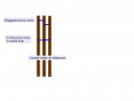
Absolutely none of the numerous 433 MHz cheapies I've worked with have given any overload/breakthru' concerns (although some have had other issues!),so IMHO arrange the antenna where wiring best suits. As mentioned before, this whip should be ~175mm for a ¼ wave vertical, & the main reasons I coil it somewhat are to make it both more compact & more visible.

The visibility issue is pretty important for a slender stiff wire at eye level- decades ago I'd ham friend poke an eye badly with a Yagi welding rod element while on a DX Field Day, & the agony the poor guy had to endure has always remained in my mind...

Dippy: Nice thoughts, but many cheapies on offer are often totally unsupported, or have Chinglish manuals awaiting translation/editing.
 
Last edited:

Dippy

Moderator
Very nasty.


Remember when calculating lengths to allow for any board track lengths, which really should be as short as possible even when doing fancy tracks on d/s.

Most Data Sheets from proper manufs give tips on antenna lengths, useful for doing coily ones where people get things wrong.
 
Last edited:

rmeldo

Senior Member
Are you talking about the transmitter MODULE or the ANTENNA?

I am talking about the transmitte module. This is because I can always move the antenna out of the box, make it vertical, remote (with screened cable I am told), etc....

However the positioning of the transmitter module would be much more complicated to move, as it is part of the packaging.

Currently I have done the packaging based on a stripboard. So there are the coppr strips on the side opposite of the module and jumper wires on the module side (Vcc, ground and data).

From the comments it seems that it likely to be OK or umpredictable a priori.

Phoning the manufacturer (Quasar, bought through RS) is a good idea (doh). I think I will do that.
 

eclectic

Moderator
@Riccardo.
From their previous forum postings,
three of the above posters are serious Tx/Rx users.
Their collective wisdom seems to be
“Just try it.”

AFAIK, you are only transmitting a few metres,
through the exterior wall of your home.

Concentrate your efforts on power-saving (code)
and element-proofing the transmitter.
Inside, just move /rotate the receiver.

And, just in case,
I know there's a store near to you.
http://www.maplin.co.uk/Module.aspx?ModuleNo=19360

(And yes, it's lossy, but you'll only need a few cm.)

e
 

Dippy

Moderator
That really is the best thing to do.
They (should) know their own product.

Here are a few tips:- (all a bit brief and pcb track examples would have helped).
http://support.rfsolutions.co.uk/faq/content/4/58/en/rf-design-tips.html?highlight=module pcb mounting

A brief tangent.....
And, not relevant, but makes me titter is:-
http://www.radiometrix.com/files/additional/lies-and-datasheets.pdf
and this is useful easy reading:-
http://www.radiometrix.com/content/application-notes

But, bottom line, get information:
A) From the Horse's Mouth, not Forum guesses. (Forum experience is a different thing.)
B) About the specific module. Packages are different. "Well, it looks the same" isn't sometimes quite good enough.
 

eclectic

Moderator
And, dare I say it, adding to post 9.

The Radiometrix engineer/guru ...

"My message here is one frequently preached: “test everything”. It is never enough to assume the claims made in a
manufacturers data sheet can be believed, unless their technical support engineers can actually substantiate the claim with
real tests.
Even then, it is vitally important to test your hardware using your aerials in your environment. Nothing else will guarantee
a reliable link. "

e
 

Dippy

Moderator
Yes, exactly ec.

Suck it and see.... it's really the only way.
But 'best practice' usually yields 'best results'.
 

manuka

Senior Member
Good points- propagation calcs. & data rate predictions may be futile unless actual field trials are conducted. Yeah- voice of experience, as I seem to have spent much of the last 5 years insisting that 2.4 GHz "b","g" (& now "n", & soon 's") WiFi claims be verified by actual "walk the talk" site surveys. (You can't beat motivating reluctant techs. by using the 1916 WW1 Somme battlefield as a planning disaster...)

At 433MHz,far & away the greatest PICAXE data hinderance however will be interference from the numerous devices (& high power radio hams) already using that spectrum sliver. In many urban regions, a UHF scanner monitoring 433.92 MHz may produce sounds akin to an African dawn chorus- especially at peak garage door/car remote/door bell times.
 

rmeldo

Senior Member
Here is my design (the format is EDrawing). You will have to change the file extension from .txt to .easm

And this is the link to the FREE viewer.

http://www.edrawingsviewer.com/pages/programs/download/

I started with a schematics, and then DIPTRACE but when I went to do the packaging it became clear that due to the box shape and the PCB mounting posts placed in the middle I would have to abandon diptrace and do it directly in 3D.

The box is the "Poundland" item about which someone tipped us off on this forum before Christmas. I can supply the IGES files if people are interested (it takes a good few hours to model).


I welcome comments, since this would be my first "tight" packaging exercise.


One thing I did but I don't know if it works is to run the ground (and other signals) around the PCB by connecting jump wires in the same holes to save space. I don't know if this is a correct technique or wether there is a better solution.


Also if the capacitance of the strips in the stripboard are unacceptable I could cut it away from underneath the module.


Riccardo
 

Attachments

Last edited:

manuka

Senior Member
Rmeldo: I'm impressed with the packaging, but best you jog our memory about just what are you doing! Was it DS18B20-08M-433TX , then thru' a house wall & 433RX-08M-LCD ? If so, the layout (providing it's compact) will be very tolerant.

However, have you FIRST done initial proof of concept trials, perhaps with it all breadboarded? Check the likes of such solderless setups as => http://www.picaxe.orconhosting.net.nz/433txrx.jpg and => http://www.picaxe.orconhosting.net.nz/all3.jpg

Keep in mind the shared nature of the 433.92MHz ISM band - interference woes can be a major issue in built up regions. Some time back -2006?-I recall Stelios (in Athens, Greece) flagging away the whole idea,due to a nearby radio ham overwhelming his flea power gear.

Don't get me wrong however, as my NZ urban experiences show that even with all manner of crazy interference (some 10km cross harbour from Wellington city), PICAXEs + 433 devices can work a treat under suitable "WAKE UP -WAKE UP WAKE UP-WAKE UP" ASCII preambles & "This is just for you" qualifiers. Your (assumed) thru' the wall setup looks almost a piece of cake!
 
Last edited:

rmeldo

Senior Member
Manuka, You remember correctly about my setup. I now put it into my own signature for convenience

I have done the proof of concept and it works for one transmitter to one receiver.

The next stage is to avoid conflict between transmitters. I have some ideas, which involve redundancy. The trade off is energy consumption. I don't want to divert this thread which is about packaging and ineterference.


So I am building a second transmitter and this time I tohught that it would be more fun to package it properly.


I would be grateful if the forum could answer my question below on prototyping:

One thing I did but I don't know if it works is to run the ground (and other signals) around the PCB by connecting jump wires in the same holes to save space. I don't know if this is a correct technique or wether there is a better solution.
Thanks

Riccardo
 
Last edited:

Dippy

Moderator
"... around the PCB by connecting jump wires in the same holes to save space. "

- sorry, I really haven't got a clue what you mean.

Maybe Stan has bigger CBs?
 

rmeldo

Senior Member
Dippy,

I attach this picture to explain my question

To connect the various component to ground in a thight packaging I thought about using a chain of jump wires like shown in the attached picture. Only done on CAD for now. I thought I would ask the forum before going to hardware, in case there might be other better ways of doing.

R
 

Attachments

rmeldo

Senior Member
No I am saying that I routed the ground and Vcc to the components which needed it by using one single row of jump wires (perpendicular to the strips)rather than staggering them.

See if this picture explains things:
 

Attachments

Dippy

Moderator
If you can physically fit things in and is electrically correct, then what do you imagine the problem might be?
Sorry, I'm having a 'thick' Sunday. I really don't understand.
I'll leave you in the Forums capable hands.
 

rmeldo

Senior Member
I don't imagine problems. I just was asking myself and the forum if there was a better way..... It seems there isn't.

Thanks

Riccardo
 

rmeldo

Senior Member
Fiddly -why not use a "Kiwi Board" style layout to start with?
I started building it. Fiddling it is.... but do-able.

Kiwi board, maybe next time. The problem was to avoid the two screws in the box for fixing the board.

Thanks to everyone for their help

Riccardo
 
Top