Hi all.
I'm not entirely accustomed to PICAXE any more and getting to grips with an 08M (just because I had one spare) with the new editor 6 was a nightmare, especially considering I nowadays use plain PIC with another Basic compiler which is just so friendly, the PICAXE was just a bugbear in comparison.
Anyways, the problem:
I have a shed which is solar powered. i.e. solar panels on the roof, charging a couple of 12V batteries and a 1000W inverter in order for me to power various tools like lathes, drills, saws and so on completely off the grid.
I also have 10 meters of LED strip lights on the inside for lighting running on a PIR sensor and a 12V amplifier for a plug-in stereo.
I would like to have lights external to the shed in front to light the area at night and would also like to have a light overlooking the fence into the garden to light the path as such but didn't want them all to run on a PIR as they would activate during the day without further modification.
The solution:
Some time ago I purchased a 433mhz remote in order to make a remote central locking system for a car, it never came to fruit though so the remote has sat dormant since. Upon opening the remote I found a 12f629 inside and a programming header. I wrestled with it for a bit to output a decent serial output but upon outputting the clock on FOSC/4 on an output pin and seeing 230khz, I knew that the chip was no good from the onset so replaced it with a shiny 12F683 and from there on it's worked a treat.
The remote outputs a qualifier such as "SHED" and then depending on the button a number like "2" or "4" in decimal, very simple.
Getting the PICAXE to recognise this was a nightmare as it doesn't automatically input decimals into variables. Wasn't until late in the night, well, morning, I realised that the picaxe needs a # before the variable in order to process it correctly.
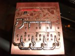
Once I'd gotten the 2 communicating with each other, I then proceeded to design the board in Diptrace and mill it with my DIY CNC Router and it came out nearly perfect.
The Finisher:
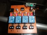
The board design itself allows a 433mhz module OR 315, to be plugged into the board. The PICAXE is socketed of course. There is a download socket and 4 relays. A 78L05 provides 5V to the board and a MMBT2222A SOT23 transistor provides switching to the relays.
There are 5 switches on the board, the first switch provides 12V source to the relays coils to enable the user to switch off the relays power whilst programming to prevent rapid switching. The other 4 switches allows the user to switch the relays on and off independent of the PICAXE.
5 LED's show statuses, for power and relay activity from the PICAXE.
Heavy traces and thick layer of solder allows the board to be used for high power purposes. The solar charger can output 10A at 12V so I would like to think that this board would be able to handle that.
A small modification had to be made to the board after completion. The board was designed to use the serial RXD in of the 08M for the 433mhz receiver not realising that the 08M doesn't allow the user to access that pin. The design has since been changed to use pin0.
A length of single core soldered to the receiver will increase the modules range.
Piccys below!
I'm not entirely accustomed to PICAXE any more and getting to grips with an 08M (just because I had one spare) with the new editor 6 was a nightmare, especially considering I nowadays use plain PIC with another Basic compiler which is just so friendly, the PICAXE was just a bugbear in comparison.
Anyways, the problem:
I have a shed which is solar powered. i.e. solar panels on the roof, charging a couple of 12V batteries and a 1000W inverter in order for me to power various tools like lathes, drills, saws and so on completely off the grid.
I also have 10 meters of LED strip lights on the inside for lighting running on a PIR sensor and a 12V amplifier for a plug-in stereo.
I would like to have lights external to the shed in front to light the area at night and would also like to have a light overlooking the fence into the garden to light the path as such but didn't want them all to run on a PIR as they would activate during the day without further modification.
The solution:
Some time ago I purchased a 433mhz remote in order to make a remote central locking system for a car, it never came to fruit though so the remote has sat dormant since. Upon opening the remote I found a 12f629 inside and a programming header. I wrestled with it for a bit to output a decent serial output but upon outputting the clock on FOSC/4 on an output pin and seeing 230khz, I knew that the chip was no good from the onset so replaced it with a shiny 12F683 and from there on it's worked a treat.
The remote outputs a qualifier such as "SHED" and then depending on the button a number like "2" or "4" in decimal, very simple.
Getting the PICAXE to recognise this was a nightmare as it doesn't automatically input decimals into variables. Wasn't until late in the night, well, morning, I realised that the picaxe needs a # before the variable in order to process it correctly.
Once I'd gotten the 2 communicating with each other, I then proceeded to design the board in Diptrace and mill it with my DIY CNC Router and it came out nearly perfect.
The Finisher:
The board design itself allows a 433mhz module OR 315, to be plugged into the board. The PICAXE is socketed of course. There is a download socket and 4 relays. A 78L05 provides 5V to the board and a MMBT2222A SOT23 transistor provides switching to the relays.
There are 5 switches on the board, the first switch provides 12V source to the relays coils to enable the user to switch off the relays power whilst programming to prevent rapid switching. The other 4 switches allows the user to switch the relays on and off independent of the PICAXE.
5 LED's show statuses, for power and relay activity from the PICAXE.
Heavy traces and thick layer of solder allows the board to be used for high power purposes. The solar charger can output 10A at 12V so I would like to think that this board would be able to handle that.
A small modification had to be made to the board after completion. The board was designed to use the serial RXD in of the 08M for the 433mhz receiver not realising that the 08M doesn't allow the user to access that pin. The design has since been changed to use pin0.
A length of single core soldered to the receiver will increase the modules range.
Piccys below!