3x PWM output
- Thread starter avner
- Start date
Andrew Cowan
Senior Member
No PIC has 3 indepenadant duty PWM outputs, however, you can use 3 08Ms to make it simple (linked via serial).
Andrew
Andrew
Yes, no PICs will do it. I'm currently driving 10 RGB LED channels using two TI TLC5940 LED driver ICs. (It's a rather rambling project for one of those interactive coffee tables)
Although using the TLC5940 for one LED maybe a bit of overkill!
Eclectic did a neat solution, sort of manual three channel PWM generation. Doesn't look too
bad with an 08M running at 8MHz
http://www.picaxeforum.co.uk/showthread.php?t=9747&highlight=RGB
- Rob
Although using the TLC5940 for one LED maybe a bit of overkill!
Eclectic did a neat solution, sort of manual three channel PWM generation. Doesn't look too
bad with an 08M running at 8MHz
http://www.picaxeforum.co.uk/showthread.php?t=9747&highlight=RGB
- Rob
Yet another option -use the pwm (not pwmout) command, which is available on the 08M as well as all of the X2 parts.
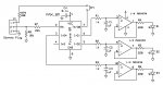
Pick three channels. Feed each of the three channels into an R-C filters, i.e. resistor R from output to capacitor C, and other end of capacitor to ground. Choose a suitable time constant - fast enough for the changes you want to produce. E.g. R=10kOhm and C=10uF should work fine (Tc=R*C=100msec).
Buffer the output of each filter with an op-amp follower (i.e. op-amp "+" input connected to the filter output, "-" input connected directly to the op-amp output, and the op-amp output connected to the respective LED through a suitable resistor (e.g. 220 Ohm).
Now issue pwm commands subsequently on each of the three channels (channel 1 - 2 - 3 - 1 - 2 - 3...). Since the pwm command returns those pins to inputs at the end of the pwm burst, the output voltage will remain stable while the other pins get updated (neglecting leakage of the input pin, the capacitor, and the op-amp input). The op-amp follower will drive this voltage into the respective LED.
Look up the pwm command for some more details.
If you use a quad op-amp for that (e.g. Maxim MAX494 or Microchip MCP6024) then all you need is the 08M plus a single op-amp chip. Ideally you'll use a rail-to-rail op-amp (both devices I mentioned are that).
On a 40X2 you could get a huge number of PWM channels that way.
Wolfgang
Just went and whipped up an experimental circuit with associated code. Works perfectly fine - the three LEDs get brighter independently, then drop back to dark and start again;
For the complete schematic, see attached picture.
Wolfgang
Code (for a 08M):
For the complete schematic, see attached picture.
Wolfgang
Code (for a 08M):
Code:
#picaxe 08M
#freq m8

symbol CYCLES = 10 ' each cycle is ~2.5 msec at 8 MHz

symbol PWM_CHAN1 = 1
symbol PWM_CHAN2 = 2
symbol PWM_CHAN3 = 4

symbol duty1 = b0
symbol duty2 = b1
symbol duty3 = b2

symbol duty_incr = 2

setfreq m8

duty1 = 0
duty2 = 85
duty3 = 170

myloop:

    pwm PWM_CHAN1, duty1, CYCLES
    pwm PWM_CHAN2, duty2, CYCLES
    pwm PWM_CHAN3, duty3, CYCLES

    duty1 = duty1 + duty_incr ' wraps around whe reaching 255
    duty2 = duty2 + duty_incr ' wraps around whe reaching 255
    duty3 = duty3 + duty_incr ' wraps around whe reaching 255

    pause 50 ' 25 msec update rate at 8 MHz

goto myloop
Attachments
-
 66.6 KB Views: 116
Well, you can if you put in a little effort and modify the code ") My code is intended as proof-of-concept to show that a lowly 08M can indeed drive 3 independent LED intensities. I spent the better part of 10 minutes at the end of a workday on it so of course that does not involve intricate intensity calculations... but uou can take it and use it as a working example for your own additions (e.g. get user intput to determine the changes, make the changes random, etc.). The hardware does not need to be modified.
My code is intended as proof-of-concept to show that a lowly 08M can indeed drive 3 independent LED intensities. I spent the better part of 10 minutes at the end of a workday on it so of course that does not involve intricate intensity calculations... but uou can take it and use it as a working example for your own additions (e.g. get user intput to determine the changes, make the changes random, etc.). The hardware does not need to be modified.
Wolfgang
My code is intended as proof-of-concept to show that a lowly 08M can indeed drive 3 independent LED intensities. I spent the better part of 10 minutes at the end of a workday on it so of course that does not involve intricate intensity calculations... but uou can take it and use it as a working example for your own additions (e.g. get user intput to determine the changes, make the changes random, etc.). The hardware does not need to be modified.Wolfgang
1968neil
Senior Member
A very useful link
no axactly pic axe, however this PIC based site has some very useful information regarding PWM and all with a PIC12F675 (similar set up as the 08M)
Hope this helps.
Regards
Neil
http://picprojects.org.uk/projects/rgb/
no axactly pic axe, however this PIC based site has some very useful information regarding PWM and all with a PIC12F675 (similar set up as the 08M)
Hope this helps.
Regards
Neil
http://picprojects.org.uk/projects/rgb/
It is possible to do RGB from a single PIC using a time-slicing method to provide soft PWM on 3 channels.
I've wrote some myself for a serially controlled RGB controller. In fact I've done a multiplexed 8 x RGB controller using an 18F2520 - but I don't think it would translate to PICAXE very well.
I've wrote some myself for a serially controlled RGB controller. In fact I've done a multiplexed 8 x RGB controller using an 18F2520 - but I don't think it would translate to PICAXE very well.
If there's enough interest I can probably whip together a simple multi-PWM controller very quickly. Probably would start out with an PIC12F683 (same chip as Picaxe 08M) providing up to 5 PWM outputs in a small chip. For LED control, a PWM frequency of maybe 100 Hz should be more than sufficient to avoid visible flicker. To get 8 bits (256 steps) of control that would mean a loop speed of close to 26 kHz. From a recent project I believe I will be able to hit that. Communication would be through a serial (RS-232) connection where you send the brightness information for each channel. Probably at 9600 baud so you can use it with any Picaxe.
Let me know of that sounds interesting.
Wolfgang
Let me know of that sounds interesting.
Wolfgang
Andrew Cowan
Senior Member
Yes, that looks indeed similar. I didn't expect that I invented something new anyway, I was pretty sure it has been done several times before. Sometimes it's fun to just go out and see if you can do it on your own - plus in this case I'll have full access to the source code. So I may just go and give it a qiuick try when I get back into my lab on Monday.
The GLCD project is currently on hold. My development board has been taken up by my new scope design, I had to disassemble the GLCD setup for that. On top of that I got into some quite complex instrument development for a (paying) customer, that's taking up most of my spare time right now - lots of fun putting a complete professional specialized grade high-frequency signal generator together from scratch! If I consider that five years ago I was just getting my first LED to blink with a Picaxe (so you see how great a thing the Picaxe is for starting out with electronic design).
Hope to get back to it when the other projects wind down, but that's going to take a few months.
Wolfgang
The GLCD project is currently on hold. My development board has been taken up by my new scope design, I had to disassemble the GLCD setup for that. On top of that I got into some quite complex instrument development for a (paying) customer, that's taking up most of my spare time right now - lots of fun putting a complete professional specialized grade high-frequency signal generator together from scratch! If I consider that five years ago I was just getting my first LED to blink with a Picaxe
(so you see how great a thing the Picaxe is for starting out with electronic design).Hope to get back to it when the other projects wind down, but that's going to take a few months.
Wolfgang
Wolfy, if you use a PIC with a USART instead you will be able to offer a PWM controller with serial control.
I did one a while back with an 18F1320 - quite cheap.
I used a byte per loop method for reading the USART buffer to have glitch-free and very fas update performance.
... in fact you could copy me, and make it 'networked' with each RGB having an address.
Eat your heart out DMX
I did one a while back with an 18F1320 - quite cheap.
I used a byte per loop method for reading the USART buffer to have glitch-free and very fas update performance.
... in fact you could copy me, and make it 'networked' with each RGB having an address.
Eat your heart out DMX
Well, turns out a 28X2 running at 40 MHz is about up to the task - but just barely. After several rounds of tweaking, here is a triple-soft-PWM driving three LEDs. The PWM code runs in a timer interrupt routine (a spin-off of my multitasking routine published a while ago), so the main program is free to calculate duty cycles, react to user input, etc. (in the demo, the three LEDs get independently brighter and then start again from dark). Although there isn't a whole lot of computing power left over. An interrupt rate of 900 Hz is about the highest I was able to achieve before it stops working. That gets you 56 Hz of PWM frequency (about the minimum necessary to avoid visible flicker) with 16 levels of intensity. Also note that in the main programs you can't use pause commands for delays because it gets terminated prematurely by the next interrupt (i.e. every 1.25msec).
A 28X1 would be slightly better than a 28X2 (in my Picaxe scope the 29X1 could handle up to 1000+ Hz interrupt). Potentially a 20X2 running it 64 MHz could get 32 levels (set counter increment to 8 instead of 16) with somwhat lower PWM frequency - I don't have a 20X2 at hand to try through.
Note that the duty cycle variablse contain the negative duty cycles (i.e. they are proportional to the time the LED is dark during a cycle). This was necessary in order to allow for a completely dark state (I had to minimize code within the interrupt).
Wolfgang
Code:
#picaxe 28x2

let dirsB = %11111111
let adcsetup = 0

symbol EVENTS_PER_SEC_DIV5 = 180

symbol DUMMY_VAL = 65536 - t1s_8
symbol TIMER_PRELOAD_VAL_DIFF = DUMMY_VAL / EVENTS_PER_SEC_DIV5
symbol TIMER_PRELOAD_VAL = 65536 - TIMER_PRELOAD_VAL_DIFF

symbol pwm_output1 = B.0
symbol pwm_output2 = B.1
symbol pwm_output3 = B.2

' for 20X2 at 64 MHz, try reducing to 8 (a bit more flicker, but twice as many brightness steps)
symbol PWM_INCREMENT = 16

symbol pwm_counter = b0
symbol pwm_duty1 = b1
symbol pwm_duty2 = b2
symbol pwm_duty3 = b3

setfreq em40

' duty cycle values range from 0...255
pwm_duty1 = 240 ' negative duty cycle (larger means darker)
pwm_duty2 = 120 ' negative duty cycle (larger means darker)
pwm_duty3 = 0 ' negative duty cycle (larger means darker)

' don't forget to intialize counter!
pwm_counter = 0

' initialize timer
settimer TIMER_PRELOAD_VAL ' set time preload value
timer = 0xffff ' generate interrupt at next overflow
toflag = 0 ' clear timer overflow flag
setintflags %10000000,%10000000 ' interrupt on timer overflow

eternal_loop:

    pwm_duty1 = pwm_duty1 - PWM_INCREMENT
    pwm_duty2 = pwm_duty2 - PWM_INCREMENT
    pwm_duty3 = pwm_duty3 - PWM_INCREMENT

    ' can't use pause command for time delays because it would get terminated prematurely by interrupt
    for w10 = 1 to 200: next w10

goto eternal_loop

interrupt:

    pwm_counter = pwm_counter + PWM_INCREMENT

    ' small weakness - even with duty cycle = 100% LED will go dark for a short moment
    ' but this cuts down on execution time, thus allows faster interrupt rate and less flicker
    if pwm_counter < PWM_INCREMENT then
        low pwm_output1
        low pwm_output2
        low pwm_output3
    else
        if pwm_duty1 < pwm_counter then : high pwm_output1 : endif
        if pwm_duty2 < pwm_counter then : high pwm_output2 : endif
        if pwm_duty3 < pwm_counter then : high pwm_output3 : endif
    endif

    ' gosub timer_setup
    ' inline code to reduce execution time
    timer = 0xffff ' generate interrupt at next overflow
    toflag = 0 ' clear timer overflow flag
    setintflags %10000000,%10000000 ' interrupt on timer overflow

return
Last edited:
hippy
Ex-Staff (retired)
The trouble with higher interrupt rates is that you end up spending all your time in interrupts so the main loop doesn't execute or only extremely slowly. That may be acceptable in some cases.
Two approaches I'd consider for increasing resolution - No idea if either would work in practice or be better, but based on simplifying the program code to make execution of the interrupt code faster ...
Use the familiar time division technique. LED 1 on for W interrupts, 2 on for X and 3 on for Y, then all off for Z to keep the loop time consistent.
Look for an interrupt mechanism which has a lower overhead. Maybe use PWMOUT to drive a hardware interrupt pin. Might have to poke SFR and use PWM in CCP mode to get an interrupt at a desirable rate.
Yes, that's the method I use too. I'm convinced it gives the best performance.
You can then put it in a loop, where the loop max value defines the resolution of your RGB values. I don't use timer interrupts at all.
With clever timing you can also look at Rx buffer (with appropriate PIC) to allow serial control and have no flicker during command update from a host.
You can then put it in a loop, where the loop max value defines the resolution of your RGB values. I don't use timer interrupts at all.
With clever timing you can also look at Rx buffer (with appropriate PIC) to allow serial control and have no flicker during command update from a host.
>Use the familiar time division technique. LED 1 on for W interrupts,
>2 on for X and 3 on for Y, then all off for Z to keep the loop time
>consistent.
Good idea hippy. Although that means the maximum achievable duty cycle for each LED will be less than 33%, instead of 100% with my routine. Not a big deal, that's like multiplexing, so just reduce the series resistors in front of the LED to increase the brightness.
I'll give it a try when I find some time.
How about something like the following? Will this be fast enough?
Code:
symbol dutyR = b0
symbol dutyG = b1
symbol dutyB = b2
symbol i = b3

symbol pinR = 1
symbol pinG = 2
symbol pinB = 3

' External loop.  Set the duty cycle in the range 0 to 15
do

  dutyR = 10
  dutyG = 5
  dutyB = 12

  high pinR, pinG, pinB

  for i = 0 to 15

    if i > dutyR then : low pinR : end if
    if i > dutyG then : low pinG : end if
    if i > dutyB then : low pinB : end if

  next i

loopvttom,
if you loom closely, that's the same as my program does. With the exception that my PWM code runs as a timer interrupt, so the main program is free to do other things. But depending on what those "other things" are they could be moved into the timer (or serial data) interrupt and the PWM execute as the main program instead; could give lower total overhead. I may try it and report back what I find.
Wolfgang
Ok, I exchanged the timer interrupt and the main program; the PWM now runs as the main program, and the user program has to run in the interrupt (timer interrupt and/or serial data interrupt). Yields about a 2x improvement in speed so with the 28X2 at 40 MHz clock I can get 50 Hz PWM frequency with 32 duty cycle steps - that's pretty usable. Note however that since the PWM gets interrupted, i.e. basically gets stopped whenever the interrupt is active, you must not spend excessive amount of time in the interrupt routine, lest you end up with noticable flicker.
Wolfgang
Wolfgang
Code:
#picaxe 28x2

symbol EVENTS_PER_SEC_DIV5 = 1

symbol DUMMY_VAL = 65536 - t1s_8
symbol TIMER_PRELOAD_VAL_DIFF = DUMMY_VAL / EVENTS_PER_SEC_DIV5
symbol TIMER_PRELOAD_VAL = 65536 - TIMER_PRELOAD_VAL_DIFF

symbol pwm_output1 = B.0
symbol pwm_output2 = B.1
symbol pwm_output3 = B.2

symbol PWM_INCREMENT = 8

symbol pwm_counter = b0

symbol pwm_duty1 = b1
symbol pwm_duty2 = b2
symbol pwm_duty3 = b3

symbol pwm_incr1 = b4
symbol pwm_incr2 = b5
symbol pwm_incr3 = b6

setfreq em40

let dirsB = %11111111
let adcsetup = 0

' duty cycle values range from 0...255
pwm_duty1 = 160 ' negative duty cycle (larger means darker)
pwm_duty2 = 80 ' negative duty cycle (larger means darker)
pwm_duty3 = 0 ' negative duty cycle (larger means darker)

pwm_incr1 = 1 ' intially increase intensity
pwm_incr2 = 1 ' intially increase intensity
pwm_incr3 = 1 ' intially increase intensity

' don't forget to intialize counter!
pwm_counter = 0

' initialize timer
settimer TIMER_PRELOAD_VAL ' set time preload value
timer = 0xffff ' generate interrupt at next overflow
toflag = 0 ' clear timer overflow flag
setintflags %10000000,%10000000 ' interrupt on timer overflow

eternal_loop:

    pwm_counter = pwm_counter + PWM_INCREMENT

    ' small weakness - even with duty cycle = 100% LED will go dark for a short moment
    ' but this cuts down on execution time, thus allows faster interrupt rate and less flicker
    if pwm_counter < PWM_INCREMENT then
        low pwm_output1
        low pwm_output2
        low pwm_output3
    else
        if pwm_duty1 < pwm_counter then : high pwm_output1 : endif
        if pwm_duty2 < pwm_counter then : high pwm_output2 : endif
        if pwm_duty3 < pwm_counter then : high pwm_output3 : endif
    endif

goto eternal_loop

interrupt:

    pwm_duty1 = pwm_duty1 - PWM_INCREMENT
    pwm_duty2 = pwm_duty2 - PWM_INCREMENT
    pwm_duty3 = pwm_duty3 - PWM_INCREMENT

    ' gosub timer_setup
    ' inline code to reduce execution time
    timer = 0xffff ' generate interrupt at next overflow
    toflag = 0 ' clear timer overflow flag
    setintflags %10000000,%10000000 ' interrupt on timer overflow

return