TC44?? Mosfet drivers has anyone used them

D n T

Senior Member
I found the Microchip TC44 series high speed MOSFET driver chips on the PICAXE VSM simulator, has anyone used them?
It seems straight forward to connect them, eight leads all labelled in the data sheet.
This will solve most of my earlier MOSFET driver issues, I would just like to know if anyone else have used them and what you think of them.
Thank you
 

Dippy

Moderator
Smaller, quicker, faster, easier, cheaper, designed by people who know what they're doing ... and they work.

What more do you want? Dunno why people faff about for weeks twiddling.
 

Mycroft2152

Senior Member
Smaller, quicker, faster, easier, cheaper, designed by people who know what they're doing ... and they work.

What more do you want? Dunno why people faff about for weeks twiddling.

I guess it's just more fun to re-invent the wheel.

A common affliction here on the forum.
 

goom

Senior Member
I'm just about to try a TC4422 driver (the 5 pin TO220 type package). Cooking an IRF530 MOSFET PWM driving a 12V motor has "inspired" me to give it a try. I may use an RFP70N03 MOSFET instead since it has a lower on resistance, but much higher input capacitance, which should not be a problem using this driver.
I'm still searching, probably fruitlessly, for a MOSFET with low resistance, low capacitance and low turn on (logic level) voltage. I'm surprised that there do not appear to be any MOSFETS with built-in drivers. It would seem to be an obvious solution.
I'll post again once I've tried it, but if Dippy has used it succesfully, then I'm fairly sure of success. The major problem will be shoehorning it into the existing PCB.
Kevin
 

evanh

Senior Member
If you're going to go down the dedicated driver road I highly recommend using an optocoupled driver with an isolated supply. These can really save a lot of damage when things don't go right with power switching. Doesn't really matter what the voltage is, once you start pushing a lot of current around you don't want the sensitive components on the same piece of turf.


Evan
 
Last edited:

Dippy

Moderator
Yes, there are quite a few MOSFETS with built-in drivers and protection.

Goom, there zillions of MOSFETS out there and unless your requirements are ridiculous I'm sure you'll find one.
What you WON'T find is a MOSFET which has the combination of high power handling (ie. ultra low Rds) and low capacitance. The bigger the MOSFET then the more semiconductor area is inside and there, by default, a higher capacitance. Physics Mate. And a higher price. Life Mate.

In a couple of power projects I'm doing right now the method I use is to parallel two or three slightly smaller Power MOSFETs. Yes, the capacitance goes up. But the advantages are: 1. Spreading the heat output into the heatsink, 2. Lower cost, 3. Having plenty of current handling capacity, 4. If one failed open-circuit then there are back ups.

So, if you can suffer the extra 2cm sq of board space (or board 'real Estate' which is a much longer and more pompous way of saying the same thing) then I feel it's better.

The driver works fine. <200nS Gate transistion speeds. But DO (yes, DO) look at the driver Data Sheet and TAKE NOTICE of the capacitor values they suggest and use a bit of common about PCB layout. For BIG MOSFETs doing Power Switching you will have several amps in and out of the Gate briefly. Do the calcs or just copy other peoples work.

I've had my design running for a week now at various loads up to 5 Amps. I need to repeat the tests up to 10 Amps so if someone could lend me a 150W solar panel that would be nice.

To get the best results you will need the following:-
1. PCB design and experience.
2. The 'proper' components. There are ceramics and there are ceramics.
3. A 'scope.
4. The patience to read Data Sheets and Application Notes.
5. A brain, or optionally the ability to copy other peoples work.
 

goom

Senior Member
Thanks for the additional information Dippy.
I have certainly come to the realisation that it's all about compromise when it comes to MOSFETS.
Fortunately, I did have the foresight to make provision for up to 3 MOSFETS in my circuit board, but unfortunately no provision for a driver. With the driver, I don't forsee any problem driving up to 5 Amps. With a low Rds, 3 MOFETS, hefty traces for the 12V supply to the TC4422 driver and a low impedance souce (7AH SLA), I suspect that heat sinking will not be required.
A much easier solution would be to buy a speed controller as sold for model cars and boats, but where's the fun and challenge in that.
I'm also experimenting with an LMD18200 H bridge driver which should be good for up to 3 Amps, and does not involve so much thought regarding PCB design and component selection.
 

Dippy

Moderator
I just realised after re-reading my post that I may have caused confusion.

When referring to currents I was meaning the brief large currents involved with driving the GATE of the MOSFET not the device load of whatever you are switching.

So many people think that 'driving' just means shoving in, but it also means sucking out.

Some of the larger MOSFETs will have thousands of pFs which means a healthy charge you have to get out from and put in to the Gate to switch it quickly. So, long thin tracks from Driver to Gate should be avoided.
AND read about the recommended capacitance that should be used as the Driver bypass. Remember, it will be briefly discharging / charging currents in the amps range, so a healthy low-impedance 'reservoir' is needed that performs well at VHFs.

The TC4422 recommends 1uF ceramic capcitor as the bypass. Whereas a lower power handling driver may only require 100nF ceramic. A bit cheaper and quite capable of driving 30 Amp rated MOSFETs.

For anyone else interested: when selecting a driver remember devices like the TC4422 are non-inverting type for easy PWM driving of N Channel MOSFETs and the TC4421 are inverting for driving P Chan MOSFETs.

The LMD18200 looks nice for small apps and obv hasall the nitty-gritty on-board so is a different thing. But, whatever power item you are using, be generous with power/ground tracks. Don't skimp just to save ink/laser-toner :)
 

evanh

Senior Member
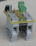
I'd like to show off one of my projects that used a MOSFET in a very simple manner. It demonstrates a robust electrical and mechanical build:

First picture is of one whole unit. This is a specially configured solid state relay for impulse sealing. It cannot sustain an ON state for very long but when it is fired it delivers a precise pulse effortlessly.

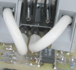
Second picture, taken upside down from the rear, is of the wires that deliver the power. They form a simple switch from one gray terminal, through the transistor, to the other gray terminal.

To give an idea of size - the transistor is a TO247 package. That's nearly twice as wide as a TO220 package. The two LED indicators in the first picture are 3mm LEDs. And that's the finished product - only a single screw used. The gray terminals clip into place.
 

Attachments

Last edited:

evanh

Senior Member
The heavy wires were chosen mainly to carry the 150 amps. But they also served as mechanical strain relief. This is vital when mounted in industrial cabinets, they tend to get a lot of thumps. And even the treatment when the sparkies are installing the units will likely break solder joins when screwing down such heavy wires into PCB mounted terminals.

Getting back to the current flowing. It is only a short pulse at maybe 10% duty. But to prevent the transistor legs from melting it was deemed a good idea to heat sink them. The easy solution was again to make use of the heavy wires, so, if you look closely, you'll see the two wires are soldered right hard up to the transistor package itself. This will quickly conduct heat away from the transistor's legs. :)

The little 8 legged package in the second picture is a combined optocoupler and MOSFET driver. The particular part was chosen for it's low supply current of 1mA as well as the isolation. The circuit totally isolates the input signal on the green terminals from the output on the gray terminals. There is a number of electrical ruggedising features in the circuit, I'll try to dig up the schematic if anyone is interested.


Evan
 
Last edited:
Top