Digital Clock

Hi guys, I am new here :)

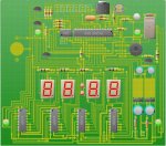
I am currently planning a little personal project, to build a digital alarm clock.
I am basing it around the 28X1, using a DS1307 RTC. However I need to find an effective and simple way to control the 4 7-segment displays.

The main requirement of the solution is that it can be left to it’s own devices while the picaxe does something else for example, so the program is not constantly having to keep the displays displaying ;)

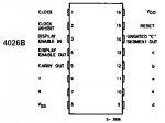
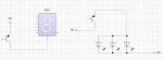
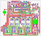
The method I have come up with is the 4015B dual 4 bit static shift register, two of these control 4x 4511 BCD decoders.

I have two main questions:
1) would this method work, and is it the easiest?
2) how does the picaxe interface with the shift register?

Regarding question 1: I don’t see anywhere that says the 4014 8 bit shift registers are ‘static’ does this mean you have to continuously send data and clock the registers? Or can you stop and start. Because I realise that 4x 8 bit registers might be more convenient than 2x 4 bit registers and 4x BCD decoders.

Regarding question 2: Is it a simple matter of taking the data pin high or low and then taking the clock pin high, and then low again. Or is there more to it such as commands that can make it simplier, or timing issues?
My plan was really to create a bunch of procedures for each number, so if after reading from the clock, I require a 4 in far right display, I run the procedure “far right 4”

Thanks in advance guys, just ask if you need me to clarify any aspects of the setup I am planning :)
 

moxhamj

New Member
There are lots of solutions. More experienced people than me will no doubt post some chips that do all this in one, and those chips (whose part numbers elude me for the moment) do make it easy.

My personal favourite is the 74HC595 as they come in at 95c each (25c each if you buy a few - type 74HC595 into www.ebay.com )You would need 4 chips =8x4=32 to drive 4 seven segment displays 4x7=28, and they can be daisy chained. Shift registers retain their outputs while the picaxe can get on with other things. They only need 3 output pins from the picaxe. Code and schematic are at http://drvernacula.topcities.com/HC595.htm

I'm sure this is fairly similar to the 40xx series shift registers.

There are no hard and fast rules or one "correct" answer. I'm sure you will get lots of good suggestions in the next couple of days.
 
Last edited:

kranenborg

Senior Member
Since you already use the i2c bus for the RTC, I would opt for a MAX6959 driver IC, as the doctor says, its combines many features in one (quite small package). Do check though if the displays you have are supported by this IC. There are different chips though.

Regards,
Jurjen
 
hey, thanks for the quick replies.

I havent really got my head around how the MAX6959 works, and what type of 7-segment display i need for it. btw, i havent bought any of this stuff yet, i am just researching atm. I intend to buy from rapid, where i could only find displays with 1 pin per led and no additional circuitry, except from this which uses the RS232 protocol, which i dont see any mention of in the MAX's datasheet.

The 74HC595's seem a bit more straight forward, need to read the datasheet in a bit more detail (it's hard not to scan when it is 27 pages lol)
 

Tom2000

Senior Member
Since you've yet to purchase any parts, take a look at the Max7219. It does what you want, and is available in a through-hole package.

Tom
 

kranenborg

Senior Member
Just want to mention that display drivers like the MAX7219, MAX6955 and MAX6959 can be sampled for free through the maxim-dallas website, sou you could experiment with a few of them, if you are interested in learning more about the SPI and I2C protocols.

The availability of code for the MAX7219 is a big pre and you should definitely consider that device, see for example the code by Tom2000: http://www.picaxeforum.co.uk/showthread.php?t=7512&highlight=max7219
Maybe there are some other code references for this chip on this forum.

The reason I would prefer the MAX6955/59 is that they offer more features (for example brightness control, and inputs with key-debounce and interrupt generation) because they are more recent devices, but most importantly they use I2C, which is generally a much more elegant solution than SPI (because i2C includes device addressing in the protocol, so no chip-select hardware is needed). Furthermore the MAX6959 is contained in a 16-pin DIP, which packs a lot of power in a tiny package. I have not used it myself (although I have it in my component box), but I have used the max6955 successfully (in an application for driving 72 LEDS separately), and the MAX6959 programming model is very similar to that of the MAX6955. I could help a bit if you need it. The MAX6959 drives standard, common-cathode 7-segment displays.

Another advantage of specialized IC drivers like MAX7219 and MAX6955/59 is that they are easier to program than shift registers, since the 7-segment code generation is performed by them. However, it is a challenge and good exercise to do it yourself ;o)

/Jurjen
 
Last edited:
Dr_Acula, i suppose now i should probably mention i have very limited knowledge of BASIC lol, i've only really used pic logicator in school and any basic has been picked up from reading things. So could you sort of explain how the code from your site for the 74HC595 works? i have annotated the parts of code i do understand :)


Code:
main:w0=%1000000010000001         word variable? = binary 1000000010000001
gosub senddatatolatch                   go to procedure: senddatatolatch 
pause 1000                                  wait 1sec
w0=%0000000000000000               word variable? = binary 0000000000000000
gosub senddatatolatch                   go to procedure: senddatatolatch
pause 1000                                  wait 1sec
goto main                                    return to start


senddatatolatch:' sends data in w0, uses register b2 and b3
' note QA is MSB and QH is LSB (binary number reads down) feed in LSB first         just explaining what the procedure does.....i dont get the b2 and b3 register thing though
    low 2' low leg 11                 outputs 0,1,2 low,  so storage clock, shift clock and serial data input pins are held low
    low 0' low leg 12
    low 1' low leg 14
    for b2=1 to 16                    when variable b2 is between 1-16:
        b3=w0 and %00000001' check rightmost bit status        erm? loads the word variable set earlier in varible b3 and add's 1 to it?
        if b3=0 then                   when the procedure is run the second time, w0 = all low and therefore: 
            low 1' serial data                   serial out w0 from output 1 (to pin 14 on the 74HC595)
        else
            high 1' serial data       if it isnt, serial out......but i dont get the high 1' or low 1', what's the difference?
        endif                            
        high 2' low to high transition stores the serial data         2 becomes high, storing the outputs?
        low 2                                returns 2 to low so it can be moved from low to high, latching the outputs on the next time this procedure is used
        w0=w0/2' shift bits to right one place          dunno?
    next
    high 0' latch the data and send it out - HC595 leg 12      dunno either.....
    low 0
    return
i'll also look into the MAX chip's soon and see if i can understand them.
 

moxhamj

New Member
Well, I could point you to the 74HC595 datasheet, but actually it makes a simple concept incredibly complicated. So to simplify, you have three lines controlling the chip. Leg 1 of the picaxe controls pin 14 of the HC595. Make it high. Make it low. It doesn't matter. But, whenever you change leg 2 of the picaxe (pin 11 of the Hc595), from low to high, whatever value is on pin 14 gets storerd.

Say you do this eight times. You now have 8 bits stored in the shift register. They are stored internally and you want to send them to the outside world. Make picaxe pin 0 high then low (pin 12 of the HC595). This "latches" those 8 bits out. If you were looking at a 7 segment display you would see the number change at that point.

Now, any binary number consists of a number of 1s and 0s. A byte has 8. A word has 16. Take a number like 00000001 in binary, which is 1 in decimal. You want to send this number out to the seven segment display (which will light up just one segment). You need to know about logic AND and OR. Logic AND says that if two numbers are equal two 1 then the output is 1. Eg, input 0 and 0 = 0, 0 and 1 = 0, 1 and 0=0, 1 and 1 = 1. In other words, both A AND B have to be 1 to make an output 1. Logic OR means if either A OR B equal 1 then the output is 1. NAND and NOR are the same as AND and OR except the output is inverted.

Anyway, if you take a binary number like 00000001 and do a logic AND with 00000001 then the output will be 00000001. If you did 11101111 AND 10101011 the output would be 10101011 - do the logic on each bit.

The line b3=w0 and %00000001 does a logic AND on the rightmost bit of the binary number in w0. The answer will be either 1 or 0. Set the pin 1 to equal this number. Then latch the bit out.

w0=w0/2 uses a bit of binary trickery which shows how binary maths ends up being simpler than decimal maths. Say you have a binary number 00000010 which equals 2. Divide 2 by 2 and you get 1. In binary that is 00000010 divided by 2 equals 00000001 which as you notice just shifts the bits right by 1. Binary 01000000 = 64 and divide by 2 = 00100000.

So, take the number in w0 and test the rightmost bit, send it out to the latch, shift it right, do it again and repeat 16 times.

For your application you would have 4 HC595 chips and you might have a 4 byte number eg in w5 and w6, and you would repeat the process 32 times. But the principle is the same.

All this will be really confusing. Let me know which bits you need clarifying! :)

The other way to explain this is to say - forget about the theory. Get a breadboard. Get a picaxe 08M. Get a HC595. Put leds (and resistors) on the 8 outputs. Put a pause 1000 beteen every line of code. Run the program and watch the leds change. I say this because this is how I got this program working.
 
Last edited:
Well, i get the first 1/2 of that post about logic and dividing by 2, however i dont really see the purpose but i suppose it doesnt really matter for my application.

The way i had planned seems a little crude but i'll explain it anyway:

I read the minuite and hour from the RTC with:
Code:
i2cslave %11010000, i2cslow, i2cbyte

readi2c 0, (b1, b2)
Then i use a whole series of:
IF b1 = 1 then goto out 1
IF b1 = 2 then goto out 2

etc, and an out1 proceedure will consist of something like
low 1
low 0
high 1
low 1
low 0
high 1
low 1
high 1
low 1
high 1
low 1

where 0 is the data, and 1 is the clock
0 is set high initially, shifted into the register, and then set low, and the register is clocked another 3 times to produce: 0001

The 4511 BCD decoder will then switch on the appropriate outputs to display a 1 on the 7-segment's.

the thing is, with this method i will have to construct procedures from 0 to 59 for the minuites and 0 to 12 for the hours. Which takes up loads of space, and takes me ages. And i have to have the same number of 'if' statements one after the other.

I actually used this on a project for school where the temperature was read from a DS18B20 and then a whole stack of if statements 0-79 found which number was read and proformed the required conversion before it was outputed.

Will this method work and is there an easier way? i dont really mind typing all that code out, provided it will fit in the end but obviously i dont want to do it unnecessarily.

finally, my orginal plan of dual 4bit registers (2 per chip, and 2 chips) could be simplified by using the 74HC595, as the 8 bit output would essentially allow me to control 4511's with 2 (or 3?) wire's rather 2 per chip (8 in total)
 

moxhamj

New Member
There is a much simpler way of doing this that uses far less code. I'm at work at the moment so I won't be able to answer it properly for the next 12 hours - maybe someone else might in the meantime.

There certainly is a much easier way though.
 
heh, i knew it was a crude way of doing it ;)

Also, i couldnt find the MAX6958/9 on rapid so although it might make a more elegant solution, if it is harder to come by, and to use i might just go with the 8 bit shift registers. But can you think of anything else that would be a cool addition to the project, anything really that uses 7-segment's as it's output (i was thinking a DS18B20 thermometer, but cant find that either)

Btw, is this 4014B a suitable alterative to the 74HC595?
 
Last edited:

westaust55

Moderator
When using the 28X1 or 40X1 microcontrollers, there is a much simpler way to shift the data into the 74HC595 shift register.

It is the Shift Out command.

Here is a code snipped taken from an example I gave in an earlier thread.
While this is used to drive 8 individual LED's, the same procedure applied when creating a pattern as a BCD code or other format to shift out to a display.

Code:
; test program to drive 8 LED via a 74HC595
; program uses the shiftout command instead of pushing bits out one at a time
; lit LED starts at the LSB (right) side and steps to the MSB (left) side
; then steps back again to the LSB side. Continues back and forth forever . . .

symbol clock = 4           ; clock on Output 4
symbol serdata = 5        ; data output on Output 5
symbol latch = 6           ; latch to 595 outputs with high pulse on Output 6
symbol bitz = 8             ; number of bits to send
symbol msb_1st = 1       ; 1 = MSB first and idle state is low
symbol pattern = b20     ; variable to hold the LED pattern
symbol delaytime = b21  ; delay between 'stepping' to next LED pattern

init: low latch
      low clock
      pattern = %00000001
      delaytime = 500    ; 500 = 0.5 sec for slow step rate. At 20 if "flies"

main:
	DO
		GOSUB out_595
		pause delaytime
		pattern = pattern <<1
	loop until pattern=%10000000
	DO
		GOSUB out_595
		pause delaytime
		pattern = pattern >>1
	loop until pattern=%00000001
	goto main

out_595:
	shiftout clock,serdata,msb_1st,(pattern/bitz)
	pulsout latch,5
	return

Edit: For a total of 4 digits if using BCD code and BCD to 7-seg chips you will need two 74HC595's. These can be cascaded to make a 16bit shift register. Then just use a word variable instead of a byte for the pattern and change the value of bitz to 16.
 
Last edited:

westaust55

Moderator
The 4014B is a serial or parallel input and a serial output.
This is not the type of shift register you want.

the 74HC595 is a serial input to parallel output shift register,
This is the type you will need to have 8 or with two 595's 16 separate outputs needs to pass BCD code through BCD to 7-Seg dispay driver chips.
 

moxhamj

New Member
Re "the thing is, with this method i will have to construct procedures from 0 to 59 for the minuites and 0 to 12 for the hours."

Break the task down into subroutines and you can save lots of space. Ok, it depends what chip you finally use, but say you were using 4 HC595s. First you need a list of the numbers - eg if you number a 7 segment display ABCDEFG going round clockwise from the top then a "7" in binary would be %11100000. You need to store the 10 numbers somewhere - put them in RAM and use an offset to find the number. Eg you might start with the segments for "0" stored at location $80 and "1" at $81 etc. Put that in a subroutine and pass one variable such as b0. Add b0 to $80 and you can then read out the number. Put 4 of these together, and send to a subroutine called HC595out which sends out (say) w5 and w6. Have a look at the bintoascii command to convert a decimal numer to a binary number to the numbers you need to send to the 7 segment displays.

The pseudo code would be:
Run two counters - minutes and hours. Both as bytes eg b0 and b1.
Take b0 (hours) and convert bintoascii
Take two right most numbers and send to the 7 seg decoder. Gives two new numbers
Do all the above for b1 (minutes).
Now have 4 numbers which are the leds that are lit for the 7 seg displays.
Send those out to the HC595.

But first you need to decide which chip you are using. The display chips people are mentioning do much of this for you.
 

Mycroft2152

Senior Member
Here's a different approach.

Look at the MC14553 its a 3 digit up counter with 7 segment decorder in a single 16 pin chip. It costs about $2US I've used it in the past.

Since your clock is basically 3 digits plus a 1, you could control the "1" separately.

Here's a link to the MC14553 used as a counter /display.

http://my.ece.ucsb.edu/bobsclass/2B/Labs/Lab 7 - 2B.pdf

Myc
 
Last edited:

westaust55

Moderator
Look at the MC14553 its a 3 digit up counter with 7 segment decorder in a single 16 pin chip. It costs about $2US I've used it in the past.
First problem there as I see it is a clock needs 4 digits, not 3 digits.


My solution for the clock data would be along the lines:

1. Read the hours and minutes from the DS13078 RTC. These come from the DS1307 as BCD coded data with two digits per byte.
2. Move the hours to say byte variable b1 and the minutes to variable b0. Leave them as BCD encoded
3. Shift the word W0 with the SHIFTOUT command to two 74HC595’s cascaded as a 16 bit shift register.
4. For the hardware use two 74HC595’s for the shift register and then use four 4511 BCD to 7-Seg display drivers. Each 4511 chip take a nybble (4 bits) from the 74HC595 outputs.
5. Over and above the Outputs to drive the 74HC595’s a fourth output can be used to latch the data from the 595’s into all of the 4511 LED driver chips.


If you want to add a DS18B20 for temperature as well then you can convert the value to BCD encoded and shift it out in a similar manner. You would use the same variables but need to set one of the two bytes to 0 (zero) abnd put the temp in the other. (of course you could use 3 or 4 digits if you want to do some extra maths and go to 1 or 2 decimal places.
 

westaust55

Moderator
MyC,

Yes, you are correct in what you say.


All,

Looking more closely at the MC14553 it still needs a MC4511 as well to drive the displays.

The counter type circuit still needs 3 digital outputs so no saving over the shift register method in terms of PICAXE I/O.

To add a tens of hours requires a further PICAXE output if I am not mistaken.
If using the counter method, first you have to check when a minute has incremented and increment the counter. Then when the count gets to 060 you have to add extra counts to get to 100. Again when you get to 160 there is a need to add extra counts to jump to 200, and so on.
Also when the PICAXE is turned off then on, it will not so elegant to resume with a display showing the correct time.

So my belief is that your chips you suggest are great as a counter but there are more elegant solutions requiring less maths etc for a clock display.
Reading the time as BCD data from the DS1307 and passing it straight out via shift registers to the 4511 BCD to 7-Seg driver chips means no adjustment, negligible maths and auto correction/resumption at the correct time immediately whenever the PICAXE is turned on.

More information of possible further use to Blue Eagle, it would also be possible to use the pulse output from the DS1307 RTC as a polled interrupt into a PICAXE input to update the display at a regular interval. Unfortunately slowest frequency is 1Hz so still 60 updates per minute (or put a binary divider IC between the RTC and the PICAXE to reduce updates per minute.

Edit:
Suggest a MC14020BCP / CD4020BCN (or just 4020) is a 14-bit/stage binary counter.
If you tap off after the 4th stage (pin 7) then you update approx every 18 seconds.
 
Last edited:
thanks for all the replies guys, some interesting ideas there.

However, can you recommend an 8 bit shift register (as similar to the 74CH595 as possible) that is available on rapid.com because i couldnt find the 74CH595 and it seems the chip to go with because of simplicity.

Btw, i was planning on using the 1Hz output on the 1307 RTC to drive 2 led's between the dual displays like you would find on most digital clocks, flashing once per second. Also the datasheet for theg 1307 says "The SQW/OUT
pin is open drain and requires an external pullup resistor" does the mean i basically treat it as ground? atm i have it connected to the negative side of the led's but am not sure if that is correct as i dont have a pull up resistor at any stage.

I think i will re-design my pcb/circuit diagrams to include the 74HC595's rather than the 4015B's. Then type some code for that and see if i am on the right tracks and understanding everything correctly. However i am a bit busy atm (exams coming up) so i dont know how long that will take.

Thanks again :)
 

moxhamj

New Member
Can you pls give the website of rapid - there are thousands of companies called rapid.

HC595 is a very common chip. Most electronic stores would have it. There are lots on ebay for 25c or so and maybe $2 shipping for a batch.

Not sure if the sqw/out needs a pullup - I never used one in this project http://drvernacula.topcities.com/lcd_clock_for_controlling_pumps_.htm

I suspect you are a long way off designing PCBs - this is going to take a bit of work on a breadboard first. Trust me :)
 

westaust55

Moderator
Digital Clock - DS1307 SQW Output

Yes the SQW output is basically (for all intents and purposes) a transistor switch pulling the SWQ Out pin low (almost to ground/0 Volts)

While you indicate that you are already operating two LED's by connecting the cathodes (negative side) of them to the SQW output of the DS1307.

In looking at the datasheet I could not see a rating for this SQW Out pin but as most of the DS1307 ratings are in the nano ampere range I would be suspect about powering two LED's at around 30 to 40mA from that pin.
For many IC's the max loading on a single output is around 25mA.

As such I would recommend the addition of the pull up resistor (say 4.7kOhm) and a NPN transistor. Then connect from VCC (+5Vdc) via a 330ohm to each LED and onto the emitter of the transistor. See the attached sketch.
 

Attachments

hey guys, sorry for the inactivity as i said, i've been busy.

I have some new questions,
how many shift register's can you 'daisy chain' together in a big long chain?
And is it a simple matter of connecting the 8th parallel output of one, to the serial input on the next?
Also, can this 8th output which is connected to the next shift register be used to drive an LED, while still passing the logic level to the next microchip?
And can you use an 8 bit shift reg, as a 7 bit, just by connecting the 7th bit to the serial in on the next chip?
 
Last edited:

westaust55

Moderator
Digital Clock - Cascading shift registers

You can basically cascade as many of these 74HC595 shift registers together as you need.
For the 74HC595 do not use the direct output from the 8t internal flip-flop (ie pin 7 = signal Qh).
There is a specific pin Qh’ at physical pin 9 which is the signal to pass on to the next 74HC595.
Suggest that you have a look at the 74HC595 datasheet
 

Attachments

Hey guys, been inactive for a while but the clock project is still alive. I have bought a bunch of stuff but have yet to get a PCB made, but am a little worried about a couple of things.

Basically i changed the design so that the displays are controlled by 4026B's, two are linked together to count the mins and two to do the hours, they will be controlled by a PICAXE 28X1.
However i have been experimenting with the 4026's on breadboard and ran into a few problems. I cannot clock the chip manually just by touching a wire to the clock pin momentarily, nothing happens and the display just remains at 0. Also pulling the reset low through a 10k causes the chip to count up very quickly, though pulling the clock pin high by touching a wire causes this count to pause, displaying whatever number it happened to be on at the time, until i remove the wire and it starts counting again.

Attached is a 4026B pinout to save you looking it up :) Atm my configuration is as follows:
1 Clock - Floating, unless touched by a wire, directly to 5v
2 Clock inhibit - low
3 Display enable in - high through a 10k
4 - float
5 - float
14 - float
15 reset - float (pulling low causes the behaviour decribed above

All the others are connected to the display or to the supply.

I read in the 4026B datasheet that the maximum clock pulse width at 5v is 270ns....however the pulsout command on the picaxe will do a minimum of 10us (10,000ns) Is this going to be a problem? will it just ignore pulses longer than the max?

ps. i ordered PNP transistors rather than NPN's by accident :( One will be used to give the displays ground (dont worry, it's rated for 2A) So do i connect the emitter to the ground of the displays, and the collector to ground, then pull the base low with the PICAXE when i want the displays on? That way the emitter is positive relative to the collector + base? Is that correct?


Thanks guys!
 

Attachments

Last edited:

Dippy

Moderator
Well, I can't comment on your breadboarding as it's not in front of me, but AFA the Data Sheet is concerned; the one I'm looking at from t.i. (revised 2003) says the clock INPUT is a MINIMUM of 220 nS.
It also says the clock speed Min --- to Max 2.5MHz.
It also says Clock Rise Fall time 'Unlimited'

All this suggests you can be as slow as you like, so a few usecs is neither here nor there.
Wouldn't worry about that aspect.

Try holding clock HIGH via a resistor and touching it low. It's looking at the transition to clock.

I think reset should be held low as well as Clock Inhibit.

Have a play. Unless you've muggered it you only have a few high/low combos to try before you get it working.
 
Awsome, that worked, seems to increment nicely now :) (though the wire bounces, but the PICAXE wont) Also pulling it low and touching it high works, which is handy because the pulse out ever 10 pulses allowing me to chain them will be high. I guess as you say it is just the transition.

Now theres just the question of the PNP transistors, i have attached a rough sketch of the way i want them to be hooked up. (in the final thing they will switch 4 displays and give high to 4 tri-colour LED's) The base's will go to the 28X1 and will be pulled low to turn the transistor 'on' and high to keep it 'off'
 

Attachments

Last edited:
Hmm......well i tried it for the display one and it works fine, i can make the display flash on and off with the 28X1. I'd assume it will work the same way for the other led's since they are basically the same thing.
 
Another update:
The person i was orginally getting the PCB done with is a little hard to get a hold of so my mate has agreed to do it for me on the CNC router where he works :)

The design i am getting made is attached and i'll post pics if anyone is interested when i get the physical thing :)


Also, after feeling the heat produced by the voltage regulator running just 1 display, 2 microchips i decided to add two of them in parallel, to hopefully share the load and not get so hot, without increasing the potential difference.
 

Attachments

Dippy

Moderator
Vroom,
have you seen the DATE of that post?
It's over 2 years old.
I doubt if Blue Eagle is really interested :rolleyes:
 

Dippy

Moderator
Eh?
My browser shows Blue Eagle's last post (no bugle) was 10th July 2008.
In my mind that is over 2 years...?

He last logged into Forum in Sept 2008.
 

westaust55

Moderator
Yeah.

I was looking at the thread by Marks that Vroom had linked to. :rolleyes:
Case of interpretation - clarity needed ;)

c'est la vie
 

Dippy

Moderator
Come one Westy... we both know that clairvoyance and Yoda-translation ability is often required here :)
Circuit designed I have haha.
 
Top