Using 74HC595 to drive 8 LEDs

westaust55

Moderator
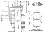
I am putting together a small module using a 74HC595 shift register to drive 8 LED’s via 3 PICAXE outputs (with my 40X1).

In searching on this forum, it seems that the usual method is to use a For … Next loop and shift the bits and toggle the data pin accordingly and also toggle the clock line.

In looking at the Shiftout command, this seems to be associated primarily with SPI serial comms but in reading up on SPI it is not essential to use all the signal lines (clock, serial out, serial in, slave select).

Therefore my question is:
Can the PICAXE shiftout command be used to drive the clock and serial data out lines to drive the 74HC595 requiring only a following Pulsout command to latch the data to the 74HC595 outputs? :confused:

Will likely get into trying code on the weekend but any prior comments would be appreciated.
 

hippy

Technical Support
Staff member
Should work. Use forum Search to see what others have done with the HC595 and other shift registers.
 

westaust55

Moderator
Hi Hippy,

I will give it a try with the ShiftOut command and see what happens.

As mentioned in Post 1,

In searching on this forum, it seems that the usual method is to use a For … Next loop and shift the bits and toggle the data pin accordingly and also toggle the clock line.
Just seems strange that in searching for 74HC595, etc, in every thread I found with code people are using the For...Next loop method and bashing it thru one bit at a time.
 

inglewoodpete

Senior Member
The 28X1 and 40X1 are (relatively) new on the PICAXE scene: hence most code discusses looping code etc.

I have been using ShiftOut with 74LS164s and 74LS595s for a few months now with a 40X1. Very quick outputs and easy to implement. You just have to use the 8 output pins (the b/w Port C pins do not support ShiftOut).
 

westaust55

Moderator
Using Shiftout command with 74HC595 to drive 8 LEDs

I can confirm that, as IWP states, it IS possible to use the Shiftout command to transfer data serially to a 74HC595 shift register to drive (for example) a set of 8 LED's. Like IWP, I have a PICAXE 40X1.
The manual (Manual 2 page159) indicates this command works with PIXAXE models 08/08M/14M/20M/18/18A/18X/28A/28X/28X1/28X2/40X/40X1 and 40X2.

Below is the test code I used today which works.

Code:
; test program to drive 8 LED via a 74HC595
; program uses the shiftout command instead of pushing bits out one at a time
; lit LED starts at the LSB (right) side and steps to the MSB (left) side
; then steps back again to the LSB side. Continues back and forth forever . . .

symbol clock = 4           ; clock on Output 4
symbol serdata = 5        ; data output on Output 5
symbol latch = 6           ; latch to 595 outputs with high pulse on Output 6
symbol bitz = 8             ; number of bits to send
symbol msb_1st = 1       ; 1 = MSB first and idle state is low
symbol pattern = b20     ; variable to hold the LED pattern
symbol delaytime = b21  ; delay between 'stepping' to next LED pattern

init: low latch
      low clock
      pattern = %00000001
      delaytime = 500    ; 500 = 0.5 sec for slow step rate. At 20 if "flies"

main:
	DO
		GOSUB out_595
		pause delaytime
		pattern = pattern <<1
	loop until pattern=%10000000
	DO
		GOSUB out_595
		pause delaytime
		pattern = pattern >>1
	loop until pattern=%00000001
	goto main

out_595:
	shiftout clock,serdata,msb_1st,(pattern/bitz)
	pulsout latch,5
	return
 

cjauvil

New Member
help with 74xx595 shift....

All the Post for the 595 shift always have a loop or a dely step in them, I am having problems with that as I would like to inc b1+1 on a button press or somthing like pin3=1 inc b1. I want to make a score board that counts to 19 using the dp(decimel) point as a "1" this way I can drive a single "7Seg" that is made of a say 35 LEDs. My team scores the kid presses the button and the display adds one more point to that team. I am having a problem with the chip or my config is sending a count up pulse on the start up can that be passed over by setting b1 to "0) after a wait 5000 for a "boot up".

PS each side is being driven by a 8m to a 74hc595 to a uln2803
 

westaust55

Moderator
Can you provide some further details about your project.

1. Which PICAXE model are you using?
2. Is the LED board already made up as a 7-segment display?
3. Can you get a few more LED&#8217;s?
4. Can you give us the circuit diagram for your LED 7-segment board?

There are other chips available better suited to driving 7 segment displays but I assume you already have the 595. Other 7-Segemnt decoder chips would have done more of the work but it is still easy.

I note that you have the uln2803 which is a high current driver to interface between the 595 and the group of LED&#8217;s for each &#8220;segment&#8221; ( a good thing :) ).

IF you are going to go the way of using a 74HC595 you have 8 outputs available, then why not use 7outputs for the first digit and use the 8th output to drive another line of LED&#8217;s as a tens digit rather than just a decimal point? Would make it easier to view.

If you have an X1 type PICAXE, that is, 28X1 or 40X1 then the SHIFTOUT command will work as per my example. Otherwise you seemingly will need to &#8220;manually&#8221; shit the bits out as per past threads.

With the schematic requested in (4) above or details of which 595 output is wired to which LED &#8220;segment&#8221; we can offer better information on a solution. Should be relatively simple once we know more specific details

With respect to the program side, you will need to have a variable that you increment each time the button is pressed. Then decode the result to get a value to activate the required segments. A series of If Then statements of a small lookup table are options here. The lookup table could do in lone command what may take 10 if statements to get the right value to pass to the 595.
 
Last edited:

westaust55

Moderator
Okay, in the absence of enough information I have taken a punt that you have an 28X1 or 40X1 model PICAXE. Here is some code to get you started:

Code:
; Qh MSB  through to Qa is LSB 
; Qh =  Tens, Qa thru Qg = segments a to g on display
;
;h         aaaaaa
;h       f           b
;h         ggggg
;h       e           c
;h         ddddd
;
; EEPROM  loc,  %hgfedcba
  EEPROM     0,  (%00111111)
  EEPROM     1,  (%00000110)
  EEPROM     2,  (%01011011)
  EEPROM     3,  (%01001111)
  EEPROM     4,  (%01100110)
  EEPROM     5,  (%01101101)
  EEPROM     6,  (%01111101)
  EEPROM     7,  (%00000111)
  EEPROM     8,  (%01111111)
  EEPROM     9,  (%01011111)
  EEPROM    10,  (%10111111)
  EEPROM    11,  (%10000110)
  EEPROM    12,  (%11011011)
  EEPROM    13,  (%11001111)
  EEPROM    14,  (%11100110)
  EEPROM    15,  (%11101101)
  EEPROM    16,  (%11111101)
  EEPROM    17,  (%10000111)
  EEPROM    18,  (%11111111)
  EEPROM    19,  (%11011111)

Symbol score = b0
Symbol pattern = b1
Symbol clock = 4         ; clock on Output 4
Symbol Serdata = 5 ; data output on Output 5
Symbol latch = 6   ; latch to 595 outputs with high pulse
Symbol msb_1st = 1
Symbol bitz = 8

Init: Low latch
      Low clock
      score = 0
      Gosub Out_595

Main:  If pin3 = 1 then             ; is button (connected to Input 3) pressed?
          Pause 5                      ; wait 5ms time for key to debounce
          If pin3 = 1 then       ; button was/still pressed ?
            Do
            Loop Until pin3 = 0    ; wait till the button is released
            score = score + 1   ; so increment the counter
	      If score =20 then   ; roll over if counter at max (19)
               score = 0
	      Endif
	      Read score, pattern   ; get the right patter to put into 595 to 7 Seg display
            Gosub Out_595  ; display updated count    ; go sent the pattern to the 7-seg
          Endif
        Endif
       Goto Main

Out_595:
       Shiftout clock, serdata, msb_1st, (pattern/bitz)
       Pulsout latch, 5
Return
If you do not have a 28X1 or 40X1 PICAXE then you will need to copy the code from another thread (you have found others) to replace my subroutine Out_595 with code to push out the pattern one bit at a time

Hope this helps you
 

cjauvil

New Member
1)I am using the 595's because they were on hand and I had a schem for them.
2) The 8m also are on hand and the least costly to do (as this is a donated project) and there is a Scem in the Picaxe programming book.(Programming & Customizing the Picaxe).
3) Ihave the board built like the drawing attatched and it is working from a protoboard to a breadboard just for programming the Pic.
4) the uln2803 alos on hand and used because i did not want to let the smoke out of the PIC or the 595 while testing and prototyping.
5) the hole thing is running off 3 AA cell Batt. planned on shifting to c or dcells for the final project.

The code I used is...

symbol dataout = 4
symbol clk = 0
symbol latchout = 2

symbol bitcounter = b1
symbol outbit = b2
symbol outbyte = b3
symbol counter = b4
symbol fifo = b0

main:


if pin3=1 then inc counter
pause 1000
end if

'if pin1=1 then dec counter
'pause 1000
'end if

'for counter = 0 to 19
lookup counter, (%01111101,%01000001,%00111011,%01101011,%01000111,%01101110, %01111110, %01001001,%01111111, %01101111, %11111101, %11000001, %10111011, %11101011, %11000111, %11101110, %11111110, %11001001, %11111111, %11101111),outbyte &#8216;binary to make 0-19 on 7 segment and dropsit into b3

gosub out595
goto main

out595:
fifo = %10000000 &#8216;We want to look at the left most bit(MSB) first
for bitcounter = 0 to 7
outbit = outbyte&fifo &#8216;Look at the MSB
if outbit = fifo then outhi &#8216;if the MSB is high output high
low dataout &#8216;else if the MSB is low output low
goto clkout

outhi: high dataout

clkout: pulsout clk, 1 &#8216;pulse the clock line to move the output bit into the register
fifo = fifo / 2
next bitcounter
pulsout latchout,1 &#8216;Dump the register into the parallel lines.
return

This was working some what but the board would count on it own some time?.? That I do not get. power it up and it would count to 4 and stay there for minutes and then I would click sw1 and it count and then wait. other times it would count a couple digits hold them then count a coupl;e more.
I think the should clear some of the fog . Hold up the switch has a 10kRes from +5v (Just added it to the drawing)
the scor almost always is less then 20 so the tens are not needed. This is for HS lacrosse. Thanx for the help I am just getting myself confused i think.


Attachments

Last edited:

westaust55

Moderator
Ah, I read it that it was more a problem with software that you wanted help with.

Looking at your schematic here are my comments:

1. Remove the 10 kOhm resistor from +5V to the common of switches.

2. Add a 10 kOhm pull down resistor to each input form switches to stop inputs floating this may be why you are getting extra counts

3. Your schematic shows one button connected to ICI pin 5. This is also being used to drive the 7-seg display. If wired that way will give you extra counts.
Should it be connected to pin 6?

Edit:
4. In going into your code since looking at schematic. You do not have contact debounce in your code?

Code:
if pin3=1 then inc counter
pause 1000
end if

'if pin1=1 then dec counter
'pause 1000
'end if
try adding contact debounce in the code as per my example otherwise you may get multiple counts on a single button/switch press
 
Last edited:

cjauvil

New Member
The Resister was the Problem I goofed when i read it This solved the problem of the mistery counts.
2) The Switch Bounce is next and the Scem was drawn wrong the reset or Dec count is on pin 6 not seven.
You are awsome- I was pulling my hair and redoing thing in code and such when it was hardware.
Thax i with post the finished stuff when i am done moving it off the bread board.
Cliff
 
Top