I thought I would show some photos of my latest project and share some links of my favourite PCB suppliers as it is becoming high time that the regular hobyist needs to "take the plunge" into using SMD components if you are going to want to keep up with the new range of chips on the market.
With picaxe chips offering I2C and SPI, it would be a shame not to use them on the myriad of ICs that are only available in surface mount. Hence a quick tutorial on how I tackle the SMD dilemma.

Here is a board that I designed in Protel Autotrax. (free download), and had made by www.pcbcart.com (US$14 each for 10 boards including shipping to Australia from China)
It's a SMD Picaxe 28x1, which reads a precision 16 bit ADC IC and then sends the reading via optocouplers to the RS485 SMD chip (MAX487). Its used to detect a photodiode and measure accurately the level of ambient light.

The smallest SMD part is a precision voltage reference IC which has less than 0.25mm clearance between pads. So to solder these without trouble, I used solder paste, found at Jaycar part number NS3037 AUD$29.95
But to ensure the solder paste did not go everywhere, I purchased a "solder paste stencil" from www.polulu.com (USD$49 inc shipping to Australia)

I emailed them the DXF file of the pad layer, and they mailed me a mylar stencil. It's essentially an overhead transparency that has all of the pads laser cut into it.
They say they need Gerber files but they were able to use my DXF which was produced by using a program called pcbtodxf.exe which is available as a free download from the same site that hosts autotrax.
I used a standard paint-scraper spatula to spread solder paste over the stencil board, then used tweezers to place the components onto the pads.
Sparkfun has a great tutorial on how to do this. http://www.sparkfun.com/commerce/present.php?p=Stenciling
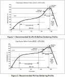
Then I used an old "George Forman" grill to reflow the PCB.

Set to its maximum setting, it gets up to 230 degrees C. This is enough to reflow the PCB.
I waited till it got to this temperature before carefully placing the populated board onto the hot plate. It took approx 60 seconds to reflow every component. I then used tweezers to take the board off the hot plate, and placed it on the table to cool down. I used the K type thermocouple on my multimeter to sense the temperature of the hot plate.
So total cost may be just a little high for a single board, but if you are making RF repeaters or things like that where you might need 10 boards or so, then the cost per board can get down to under $20.
Pretty good considering you get to utilise SMD chips that you may have put in the too-hard basket, and you get a really professional looking result when you are done.
I hope this has helped others to give SMD soldering a try.
With picaxe chips offering I2C and SPI, it would be a shame not to use them on the myriad of ICs that are only available in surface mount. Hence a quick tutorial on how I tackle the SMD dilemma.

Here is a board that I designed in Protel Autotrax. (free download), and had made by www.pcbcart.com (US$14 each for 10 boards including shipping to Australia from China)
It's a SMD Picaxe 28x1, which reads a precision 16 bit ADC IC and then sends the reading via optocouplers to the RS485 SMD chip (MAX487). Its used to detect a photodiode and measure accurately the level of ambient light.

The smallest SMD part is a precision voltage reference IC which has less than 0.25mm clearance between pads. So to solder these without trouble, I used solder paste, found at Jaycar part number NS3037 AUD$29.95
But to ensure the solder paste did not go everywhere, I purchased a "solder paste stencil" from www.polulu.com (USD$49 inc shipping to Australia)

I emailed them the DXF file of the pad layer, and they mailed me a mylar stencil. It's essentially an overhead transparency that has all of the pads laser cut into it.
They say they need Gerber files but they were able to use my DXF which was produced by using a program called pcbtodxf.exe which is available as a free download from the same site that hosts autotrax.
I used a standard paint-scraper spatula to spread solder paste over the stencil board, then used tweezers to place the components onto the pads.
Sparkfun has a great tutorial on how to do this. http://www.sparkfun.com/commerce/present.php?p=Stenciling
Then I used an old "George Forman" grill to reflow the PCB.

Set to its maximum setting, it gets up to 230 degrees C. This is enough to reflow the PCB.
I waited till it got to this temperature before carefully placing the populated board onto the hot plate. It took approx 60 seconds to reflow every component. I then used tweezers to take the board off the hot plate, and placed it on the table to cool down. I used the K type thermocouple on my multimeter to sense the temperature of the hot plate.
So total cost may be just a little high for a single board, but if you are making RF repeaters or things like that where you might need 10 boards or so, then the cost per board can get down to under $20.
Pretty good considering you get to utilise SMD chips that you may have put in the too-hard basket, and you get a really professional looking result when you are done.
I hope this has helped others to give SMD soldering a try.


