any advice on small robots?

jwhooper

Senior Member
This year, my wife started a FIRST robotics team for home schoolers and I am the mentor programmer (my two sons and daughter are on the team as well). As a rookie team, we are unlikely to finish the actual robot with much time to spare, since we only get six weeks. Without the robot, we can't test any software, and for autonomous mode we might try to implement some ultrasonic sensors, which mean signal filtering and a fairly complex algorithm for navigation.

It might just be possible to build a smaller model of our robot and test out the ultrasonic sensors using a picaxe18. It would need to control two motors and up to three ultrasonic sensors and maybe one or two other sensors.

I am looking at gearboxes and motors. I don’t need a “Low-voltage motor controller” do I? I think the picaxe can do that.

Thanks for any advice, tips, or helpful suggestions.

I have had the pleasure of completing two picaxe08 projects, a biofeedback "hand warming" trainer and a ECS (electro cranial stimulation) unit with help from this board. This truly proves that with the picaxe, anybody can do it!
 

MurrayJ

Senior Member
Check out he Picaxe 18 high power project board. It has two reversable motor outputs that can handle 1 amp each. Also with the ultrasonic sensor, did you consider mounting one on a servo? you could get the required coverage using only one ultrasonic sensor, depending of course why you wanted three in the first place.
 

demonicpicaxeguy

Senior Member
Also with the ultrasonic sensor, did you consider mounting one on a servo? you could get the required coverage using only one ultrasonic sensor, depending of course why you wanted three in the first place.
somone did a ultrasonic radar with that, from what i remember it turned out quite well
 

jwhooper

Senior Member
Thanks for the input! I was going to use three because the competition is a lot like a race around an oval track, only there will be five other robots and four large balls on the track as well. My simplistic way of approaching the problem of going counterclockwise around a track and avoiding obstacles would be to point a sensor straight ahead, 45 degrees to the left, and directly left, 90 degrees. I thought that if the robot always moved towards the longest opening, it would make it around the track and avoid some obstacles.

I would have preferred laser rangefinders but they aren't allowed. I know that the ultrasonic ones have a spread, which might not be good. Human operation is allowed after the first 15 seconds are up, but then the large bonuses are over.

A lot of teams will just count gears and pre-calculate the turns. I'm sure this will work out, but the idea is for the kids (high school age) to learn something so I think having some intelligence built into the navigation would be far more valuable in that regard.

I have never used an ultrasonic sensor before, so I actually have no idea how they will function in practice.
 

jwhooper

Senior Member
Check out he Picaxe 18 high power project board. It has two reversable motor outputs that can handle 1 amp each. Also with the ultrasonic sensor, did you consider mounting one on a servo? you could get the required coverage using only one ultrasonic sensor, depending of course why you wanted three in the first place.
I was going to go with the low power, "Dual Motor GearBox" which is pretty complete, but I don't think it needs high power, does it?

At Sparkfun, they have the Maxbotix ultrasonic range finders, which don't seem to need all that much power either, although they do warn "The serial interface is a bit odd (it's RS232 instead of standard TTL), but the PWM and Analog interfaces will allow any micro to listen easily enough." That isn't a problem for the picaxe though, as I understand things, which admittedly isn't very well.

The actual competition robot might be moving along at about 10 feet per second, so I could mount the sensor on a servo and sweep around, but I'm not sure if that would be fast enough. It would look cool, though.

I know a lot more about programming than electronics.
 

eclectic

Moderator
Read first; then check.

JW. I don't know much about robots, but I have fried Picaxes before now!

Any motor that can drive body/sensors/batteries etc. at 10 m/s
is guaranteed to use more than 20milliamps.
That is the MAXIMUM current that any pin on a Picaxe can provide.
A "power" circuit is essential. Please see manual 3 (Interfacing).

Please read the datasheet for your motors, or even better, publish the link here.

On the Ultrasonics, can you source the SRF05 at a reasonable price?
There's plenty of information (circuits and program) on this site.

hth
e.
 

jwhooper

Senior Member
Well, I am talking about two robots here. One is the competition robot, which is definitely a high powered device. My interest here is in building a more modest robot, just for testing the navigational system and software.

A friend of mine who is an electrical engineer proposed that buying a remote control car might save me a lot of trouble. The trick will be to interface my picaxe/ultrasonic sensor navigation system to a commercial product.

I suppose the easy way would be to hack the remote control and have the picaxe simulate the speed and direction. Then I could just attach the remote control with its picaxe and sensors to the car ... better make it a truck, actually.
 

Rickharris

Senior Member
We build a simple 08 + L293 motor controller robot at school. A flat Ply wood or MDF chassis. 2 Motor gearbox combinations hot glued on the bottom with suitable wheels (I prefer Lego wheels but we use a cheaper option.)

A basic PCB with the picaxe and download cct is connected via screw connectors. I can build one in about 1/2 an hour - the students take about 12 hours.

Add a second Picaxe 08 for the u'sonic control or use an 18 or 28 and your away - will try to get some photographs of current models at school tomorrow.

Cost about £7 if you buy all the bits.
 

jwhooper

Senior Member
We build a simple 08 + L293 motor controller robot at school. A flat Ply wood or MDF chassis. 2 Motor gearbox combinations hot glued on the bottom with suitable wheels (I prefer Lego wheels but we use a cheaper option.)

A basic PCB with the picaxe and download cct is connected via screw connectors. I can build one in about 1/2 an hour - the students take about 12 hours.

Add a second Picaxe 08 for the u'sonic control or use an 18 or 28 and your away - will try to get some photographs of current models at school tomorrow.

Cost about £7 if you buy all the bits.
I do have several spare Picaxe 08 chips. My problem is that I know so little that I need a fairly complete parts list and instructions. Is a motor controller always necessary? I thought the picaxe could drive a motor. Or does the controller supply the extra power?

Maybe you already have all of this documented for your students, in which case I might have a chance!
 

Rickharris

Senior Member
I do have several spare Picaxe 08 chips. My problem is that I know so little that I need a fairly complete parts list and instructions. Is a motor controller always necessary? I thought the picaxe could drive a motor. Or does the controller supply the extra power?

Maybe you already have all of this documented for your students, in which case I might have a chance!
The picaxe will only provide 20 MA per output and a total of 100Ma per chip.

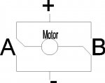
To drive something as meaty as a motor you need either transistor/MOSFET if you don't need to go in both directiond or a motor driver H bridge (generally the L293 does the job well). the h Bridge allows the motor to go both ways - as a 3rd option small low power relays could be used.

In the attached diagram A and B are relays - Switching them will change over the + and - connections to the motor - This is an H bridge. It can also be made with transistors but is easier to buy the L293.

Will look out an E copy of documentation we use. Tomorrow. :)
 

Attachments

Rickharris

Senior Member
OK Found the Booklet - I have converted it to a PDF file.

The programme we generally end up with is something like this

Code:
Start:
high 0
High 2 ' move forwards

if pin3=1 then turn
goto start

turn:
low 0
low 2 ' stop
high 1
high 4 ' go back
wait 2 ' controles how far it backs up
low 1
low 4 ' stop
high 4 ' turns way from obstruction
wait 4  ' controles how far to tunr.
low 4 'stop
gogto start ' go forwards again.
This is a simple application of Bump and go but can easily be expanded to ultra sonic control, I/R control or I/R Sensing.
 

Attachments

jwhooper

Senior Member
Thank you very much Rick. This makes all the difference. I am going to order the parts and probably a picaxe 18 so I don't have to figure out how to use two picaxe 8 chips together.

Again, it is very kind of you to go to this trouble. I will keep the board posted on my progress and hopefully I'll be able to share a nice finished product and some code.

I have ordered the entire range of the MaxBotix ultrasonic sensors, so it will be interesting to compare them as they all differ in beam shape somewhat.
 

profmason

Member
If you are near Los Angeles, our picaxe sumo school starts on Friday. It consists of 5 two hour sessions and is targeted for our local high school students. I am also mentoring a first technical team (Which uses the VEX platform). Here is a basic outline of the sumo school:
Week 1:
Building a Picaxe Dev Board
http://profmason.com/?p=218
Week 2:
Building Tamiya Dual Motor
http://www.pololu.com/products/tamiya/0061/
Using an Hbridge for motor control
http://profmason.com/?p=243
Week 3:
Building Sensors: First a sumo ring sensor from a IR emitter/phototransistor pair:
http://profmason.com/?p=378
Using the SHARP GP2D12 IR sensor
http://www.acroname.com/robotics/parts/R48-IR12.html
Week 4:
Building a chassis and putting it all together
Week 5:
Testing and refinement

The Saturday Following Week 5 is a competition held at the Robotics Society of Southern California meeting. Here is a link to the competition rules:
http://profmason.com/?p=374

Here is a picture of one of the robots from the last sumo school:
http://profmason.com/?p=320

I got a bit of a mini-grant to put this on, so I provide each of the participants with a baggie of parts etc.

On one final note, I have used the MaxSonar sensor, it works great, but has a pretty wide angle of detection. (Basically you know "Something is out there") The Sharp IR sensors are much more precise. (The GP2D12 is the classic out to 1 meter) Sharp has a new sensor (Sharp GP2Y0A) that has range comparable to the sonar sensors (1 to 5.5 meters) but with a much smaller detection "beam" then the sonar sensors.

have fun!
 

jwhooper

Senior Member
Thank you for the information. I ordered the Maxbotix ultrasonic sensors (they have five with different beam shapes). I was worried about the broad beam, but some teams that have used them before didn't find this to be a huge issue. All we really have to do is detect a wall and other large robots and avoid them. The arena is 54' x 27', so I needed distance a lot more than precision.

This is what I ordered from Sparkfun to build my personal robot:

1 x ROB-00423 : Toy Tires - Basic
1 x ROB-00319 : Dual Motor GearBox
1 x COM-00315 : H-Bridge Motor Driver 1A
1 x DEV-08316 : PICAXE 18 Pin Power Project Board
1 x COM-08309 : PICAXE 18 Pin Microcontroller
1 x PRT-00550 : Battery Holder - 4xAA Cube

I'll be looking at your info very carefully when it all arrives. I always have monumentally basic questions like: Two wheels will fit on the dual motor gearbox, but how do I make an axle for the other two wheels? Front wheel drive is better, right?

The actual competition robot will have a chain driving a front and back wheel on both sides, so it will turn like a tank basically. I'm trying to stay as close to that as possible, within reason. My robot should turn in the same way I think.
 

profmason

Member
For the other two wheels.... don't use two, a single point works great. Something as simple as a 1 1/2" bolt threaded into a nut through the platform will work as a 3rd point of contact. Better is a caster and even better is a ball caster. Tamiya makes a ball caster that is designed to work with there motor kits. Almost all the small robots that we make use a pair of wheels for differential drive and a single caster as a 3rd point of contact.
ball caster link:
http://www.hobbylinc.com/htm/tam/tam70144.htm
if you really want a second pair of wheels, you can buy inexpensive kits which comes with various length hex axles for the tamiya wheels and right angle pieces which the axles fit into and then bolt to the chassis.
http://www.hobbylinc.com/htm/tam/tam70098.htm and
http://www.hobbylinc.com/htm/tam/tam70105.htm

Eventually you get enough of this stuff around that you can solve most problems. Using the Tamiya stuff will save you LOTS OF TIME AND GRIEF!

BTW we had 17 folks show up at the sumo school and they put together 12 picaxe dev boards. Inside of two hours 11 of the 12 had blinking leds.

have fun!
 

Rickharris

Senior Member
Lots of DIY shops have small ball castors or ball spring cupboard catches that can work as well.

Lego castor wheel is great if you have one.
 

jwhooper

Senior Member
Thanks for the advice. I will design for three wheels. I'm sure I can find a caster. On Monday we are going to build with another team that mentioned they have a lot of wheels from many years of competitions, so they might have a caster.

My gearboxes and wheels are all Tamiya.

Glad to hear the sumo school is off to such a great start. I must admit, if it weren't for the picaxe and help from this board I would have abandoned electronics a long time ago. Nothing builds confidence like a simple project that works.
 

tarzan

Senior Member
Old spoon as third wheel. (skid)

Use of an old spoon comes to mind. Actually I used two one front and one rear.
 
Last edited:
Top