Bob Champagne
New Member
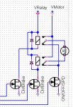
Hello everybody. I have limited experience with Picaxe and programmation so need help with this project. I need to control direction and speed of a 12 volt washer wiper motor, so I built this PICAXE 08M controled H-bridge with 2 relays activated by 2n7000 mosfets and PWM by P50N06L mosfet. All mosfets are logic level. I already have etched and soldered all components on the PCB. The forward and reverse work good but I can't get no PWM.
The code I use (OK you can laugh all you want..) is:
SYMBOL ADCVALUE = W1 ;ASSIGN WORD 1
READADC10 4,ADCVALUE
PWMOUT 2, 49,ADCVALUE
GOTO MAIN
MAIN:
HIGH 0
LOW 1
PAUSE 5000
LOW 0
LOW 1
PAUSE 2000
HIGH 1
LOW 0
PAUSE 5000
LOW 0
LOW 1
PAUSE 2000
GOTO MAIN
How do I write a code that will PWM the High pin only?
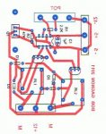
I attached the general schematic as well as the actual traces on the PCB.
Thanks in advance for your help.
The code I use (OK you can laugh all you want..) is:
SYMBOL ADCVALUE = W1 ;ASSIGN WORD 1
READADC10 4,ADCVALUE
PWMOUT 2, 49,ADCVALUE
GOTO MAIN
MAIN:
HIGH 0
LOW 1
PAUSE 5000
LOW 0
LOW 1
PAUSE 2000
HIGH 1
LOW 0
PAUSE 5000
LOW 0
LOW 1
PAUSE 2000
GOTO MAIN
How do I write a code that will PWM the High pin only?
I attached the general schematic as well as the actual traces on the PCB.
Thanks in advance for your help.
Attachments
-
 73.9 KB Views: 44
 -
 55.5 KB Views: 25
")