I'm working on the basics of a weather monitor ("O noes!", I hear you scream...) that, for now, will be powered by three AA batteries. I will eventually convert it to solar power but I'm waiting to put an order in to SparkFun that will have the necessary parts. So, for now, I'm powering it off of the AAs and I want to figure out how long it'd last on one change of batteries. I bought two MAX6018B V. Ref. chips, to be able to accurately monitor the battery voltage. However, I'm having problems with the math...  .
.
With a quick search (there's a search bar?)I found a post by kranenborg with the math necessary to convert 8 bit ADC readings to a mV voltage level. However, he used the 1.2V version and I'm using the 2V version of the V Ref. chip. I know, I probably should have gotten the 1.2V but I didn't and it'd take a couple weeks (if not months) for a package to arrive...
Anyways, I changed the math around somewhat to give me a somewhat accurate reading (within ~100 mV), but it's not accurate enough for me. And, I can't wrap my head around it well enough to change it to my liking. I'd like it accurate within 30-40 mV like the original code, even if it means using the 10 bit ADC and a word variable to store the value in.
This is my modified code.
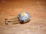
P.S. I soldered the MAX6018 and required cap to a 3-pin header, to make it easier to move between designs.
.With a quick search (there's a search bar?
)I found a post by kranenborg with the math necessary to convert 8 bit ADC readings to a mV voltage level. However, he used the 1.2V version and I'm using the 2V version of the V Ref. chip. I know, I probably should have gotten the 1.2V but I didn't and it'd take a couple weeks (if not months) for a package to arrive...Anyways, I changed the math around somewhat to give me a somewhat accurate reading (within ~100 mV), but it's not accurate enough for me
. And, I can't wrap my head around it well enough to change it to my liking. I'd like it accurate within 30-40 mV like the original code, even if it means using the 10 bit ADC and a word variable to store the value in.This is my modified code.
Code:
	#rem
	Original program by kranenborg @ http://www.picaxeforum.co.uk/showpost.php?p=95202&postcount=3
	Modified to make it easier for me to read... and to work with a 2048 mV reference instead of 1263 mV.

	Original text: "Calculate Battery level (Vcc. in mV) using Vref (1263 mV at 25 degr. C) delivered
	by MAX6018. Only 8-bit ADC value is used, accuracy for calculated Vcc in the
	critical range of 2.0V is approx. 10mV, for Vcc of 3.6 (maximum battery voltage) the
	error is approx 40mV.

	Calculation formula: Vcc(mV) = 1263mV (Vref) * (255 / ADC_Vref)
	  			        = (1263 * 51 * 5) / ADC_Vref
	 			        = (64413 / ADC_Vref) * 5
	Note that 16 bits integer calculus is used using as large integers possible
	before a division is done, in order to minimize round-off errors"
	#endrem

ReadV:	let w1=0
	readadc 1,b0
	let w1=10240/b0
	let w1=w1*5	;Vcc calculated in mV's
	sertxd (#w1,13,10)
	pause 2000

	goto ReadV