Sound, amplification, LM386 and a Picaxe08m....

Anobium

Senior Member
I have a relatively simple question?..

What it the correct method to build a simple Picaxe volume control for the project I am building?

Why am I asking for help? I have spent many hours in the last week trying to figure out the best method.

Requirement: Volume control for an amplified sound output using a Picaxe 08m which is using the tune basic instruction to an 8 ohm magnetic/coil speaker.

What I know.

I can implement a simple volume control by placing 33R resistor in series to generate a total resistance of 41R (as per the documentation) to the + side of the speaker, then implementing a 50k pot across the two connectors of the speaker. This works.​

What I cannot do is amplify and control.

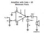
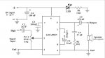
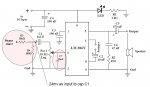
I was to implement a simple M386 amp but I cannot get the sound stable. I get volume control via the 10k pot on the input to LM386 but I cannot shut the sound off and at the full range of 10k the sound drops of instead of increasing.​


Arghhhh!!! What am I doing wrong?

Thank you in anticipation.
________
 
Last edited by a moderator:

russbow

Senior Member
you should use a log pot, not a linear.

It is good to put a 10 uF cap between the picaxe output and the pot, -ve lead to pot.

Make sure your 0 volt lines of the amp and the picaxe circuit are connected together.

If you find the control is "one ended" just changeover the top and bottom pins of the pot.
 

Anobium

Senior Member
Ok, I will go and get the 10k Log pot from Mzplins today.

I will revert with the results tonight.

:)
 
Last edited by a moderator:

russbow

Senior Member
I use this simple circuit for interfacing to the picaxe. Not really looking
for hi-fi quality.

Page 5 of the datasheet gives further circuits if you need more oomph.
 

Attachments

Anobium

Senior Member
Yes, this circuit work great for sound out of my laptop. I get full volume control but... out of the Picaxe I get limited volume control with near silence at both extremes when I adjust the pot.

Now I am thinking.... Am I being dumb?

1. Is the pot shown on the diagram the volume control? Yes, it is because I get smooth volume control from my PC playing an MP3.
2. Why does the same circuit operate differently when I use the Picaxe as a source? Dunno....
[/LIST]​

Keep helping everyone. Thank you.
 
Last edited by a moderator:

russbow

Senior Member
limited volume control with near silence at both extremes when I adjust the pot
At one end I would expect near silence, it's turned down to minimum.
At the other end it is possible the amp is being overloaded.
Change the input capacitor to 100nF or so. Try adding a 4K7 resistor between the cap and the top of the pot. This will create a potential divider such that at max, you will only put about 2/3 of the signal in.
 

Anobium

Senior Member
Update

I have reviewed the circuit. I have implemented the circuit as attached,
.

I also built a signal gernerator to test these circuits and the circuit shown in the attachment works like dream for audio output from my laptop and pda.

However, when attach to the Picaxe I limited sound control, with all the control in the first few degrees of the pots movement, then its very loud.

I did change C1 for a 10uf eCap and this make no difference.

Oh why? What am I missing?
 

Attachments

Last edited by a moderator:

InvaderZim

Senior Member
How is it hooked to the Picaxe exactly? Are you using PWM or TUNE or something? You may need an additional bit between the Axe and the amp.
 

russbow

Senior Member
I suspect you are driving the amp far too hard.
The picaxe output will swing between 0v and supply. don't forget, you are looking at a digital signal, not a nice AF waveform.

As I said before, reduce your input cap to 100nF or even less.
Put a 4K7 ( or bigger ) resistor between the cap and vol control to attenuate the signal. The amp chip does not need volts to drive it, more like milli volts as you get out the earphone socket of you laptop.
 

Anobium

Senior Member
Getting somewhere...

See the attachment, this shows the revised circuit.

I addition of the second pot (see diagram) enables me to set the output voltage from the Picaxe to 50mv. Then, all is stable!!!!

So, I need to limit the input to the amp from the Picaxe at 50mv. I believe the additional 10k lin. pot is a potential divider but I do not know why this works.

What is the best method to assure 50mv into the amp? Or, I am doing it wrong?

More help and insights please.
________
 

Attachments

Last edited by a moderator:

moxhamj

New Member
The LM386 I think has a fixed gain of 20. So if you put a 5V signal in from a picaxe, you get 100V out. This then gets clipped to the 9V of the supply rail

A small speaker might be only 0.1W. 8 ohms, V=IR, V=0.8V.

That is the output, so divide by 20 to get the input which is 0.04V. That is 40mV which is very similar to the 50mV you have calculated.

So if the picaxe output is 5V and you want to turn it into 0.04V, then I think that is 5/0.04 which is to divide by 125.

If you have a 10k volume pot, I'm thinking maybe you need a 1.25 meg resistor in series??? (a 10k only divides it by two. Not enough)

Maybe not quite that much, and maybe I made a mistake with the maths.

When a pot goes right to one end, I don't think it quite connects to zero, so maybe that explains why a bit of volume gets through.

I'd experiment with resistors at the top of the pot in series - try some over a big range, a 10k, then a 100k, then a 1meg. See which seems to work the best.

I'd be interested to see what value works as I'm working on a very similar circuit at the moment.
 
Last edited:

Anobium

Senior Member
I know am getting a better understanding.

Have a look at my previous post as the revised circuit is controlling the volume, by limiting the volts to 50mv. But, I need to understand why the additional pot works and whether there is a simplier solution.

re comment.. InvaderZim ... I am using the Tune command.
re comment.. russbow .... I tried the 4k7. This does not seem to work as the voltage remains too high. I am missing understanding your advice.

Thanks.
 
Last edited by a moderator:

hippy

Ex-Staff (retired)
Have a look at my previous post as the revised circuit is controlling the volume, by limiting the volts to 50mv. But, I need to understand why the additional pot works and whether there is a simplier solution.
It's not clear to me how that pot is actually wired from the attached image but it doesn't look 'safe' to me.

What it seems you need to do is limit the input to the amp to this 40mV or so, and the way to do that is by using a potential divider. The top will be a fixed resistor, the bottom will be your variable pot. With the wiper at the top you'll get the full 40mV from the PICAXE 5V output, as the wiper moves down you'll get less and the volume decreases.

It should be normal potential divider maths, just that you have to fit the top resistor to match a more limited range of resistance values a pot tends to have.
 

MartinM57

Moderator
Use one simple potential divider immediately on the output of the PICAXE, then feeding the amplifier.

Fixed top resistor, variable bottom resistor, junction to amplifier

Use the third set of calcs at http://www.electronics2000.co.uk/calc/potential-divider-calculator.php

V1 = 5 volts
V2 = 40 mv
R2 = 10K (i.e your 10K pot at maximum value)
...gives R1 (the top resistor) of 1.2Mohms - just like Dr Ac said....

When the pot is at the top, close to 10K, the output of the divider will be 40mv.
When the pot is at the bottom, close to 0R, the output of the divider will be virtually zero.

I've no view on what the capacitor on the input does .... it's probaly quite complex how it affects "digital audio" (i.e 0v and some other voltage and just switching between them) depending on it's value - you need an analogue sound engineer to get a definitive answer.
 
Last edited:

russbow

Senior Member
I think Martin it's a throwback to the good old audio days

I've no view on what the capacitor on the input does .... it's probaly quite complex how it affects "digital audio" (i.e 0v and some other voltage and just switching between them) depending on it's value - you need an analogue sound engineer to get a definitive answer.
Gives DC isolation between the detector / pre-amp anode (collector) and the audio input.

No real use in the picaxe I suspect but I'd still put one in. Just feels right
 

MartinM57

Moderator
But "DC isolation" is a moot point when the input is only DC voltages (0v and 40mv) with rapid rise/fall times in between.

If that American guy was still around, he'd have some SPICE model output for us showing what appears at the amplifier compared with the PICAXE output signal for different C values...
 

sghioto

Senior Member
You need the input capacitor to block the DC from the LM386 input circuit. A DC level above a certain value will actually shut the amp off. I've seen just this type of arrangement configured as a squelch control using the LM386 in some handheld scanners.

Edit: In this case as MartinM57 wrote DC isolation is mostly a moot point at those low DC levels. However it does affect the input bias on the LM386 which affects the output DC voltage. In this case using a 5 volt supply a 50mvpp signal raised the output DC level from 2.55 volts to 3 volts. But since the signal is basically a square wave no harm done again. Bottom line, you can leave out the coupling capacitor. Actually, connecting a .01uf capacitor from pin #3 to ground on the LM386 will clean up the DC spikes on the audio output for a "cleaner" sound.

Steve G.
 
Last edited:

Anobium

Senior Member
It works

Thank you.

I have created a 'valid' potential divider to provide input to the capacitor of 24mv from the outut of the Picaxe.

I also added the additional capacitor as recommended by Steve G from the output to ground.

All works great!

I have attached the final working diagram for future reference by others.

Thank you all.
 

Attachments

Last edited by a moderator:
Top