We are now falling into the murky depths of that "black art" of battery charging

My first hand knowledge based on many years of experience of battery charging only applies to older technologies. ENELOOP have only been around for a few years (at least in my hands) so my knowledge of them is limited.
So, what I'm about to say is applicable to NiCd and early NiMh technology but might also apply to ENELOOP technology.
Once fully charged, any energy which is subsequently put into a battery does nothing except break down the electrolyte into gas. If left unchecked, this would eventually build up enough pressure to pop the release valve (or explode the battery) and discharge electrolyte into the atmosphere thus reducing the capacity of the battery until it eventually dries out and becomes useless. To prevent this, the manufacturers make the negative electrode bigger than it needs to be and a few extra chamicals that recombine the gas back into the electrolyte. However, this process has a limit and is usually only capable of working at currents under C/10.
The larger the battery capacity for the same physical size means less free space for excess negative electrode. So, larger capacity batteries can only handle SMALLER charge and over charge currents. (the opposite of what many people assume).
Most manufacturers state that an indefinite charge current of C/10 will cause no damage but this is worth checking for the specific battery you have.
In applications such memory or clock battery backup where the battery is nearly always on charge, in the past I have recommended much lower charge currents. However, with recent batteries where more and more has been crammed in to obtain higher capacities, it has been done at the expense of insulation layer between the electrodes. When charged very slowly, the crystals grow larger than at higher currents. These (known as dendrites) can grow large enough to puncture the insulation and cause internal shorts at low charge currents.
So, to put it simply, there is no simple answer. That's why there are a whole host of very clever battery charger chips out there and many different oppinions on how it should be done. Bottom line, it depends on your specific battery.
As you have already looked at ENELOOP cells, I'm guessing that you are also aware of the (relatively) fast self discharge rate of NiMh. Standard NiMh will self discharge at around C/200 to C/300. ENELOOP are several orders of magintude better. So, there are now two factors which determine MAXIMUM battery size and one which determines MINIMUM battery size for a simple constant current(ish) setup.
I've never tested ENELOOPs at long term constant current.
However, I'd bet that they are safe anywhere between C/10 and C/20.
Go on, make an intelligent charger. You know you want to!
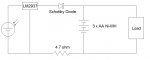
 47.3 KB Views: 176