Help with HPWM

cactusface

Senior Member
Hi Folks,
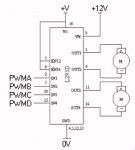
Just started on my second BuggyBot, hoping to use a 20x2 but will be testing on a 40x2 has this I have at the moment. I intend to use PWM in the form of HPWM, but having looked at the command! I'm a littleI lost. Most likely I will use an L293 driver for 2 small DC motors and use PWM on the enable pins. As I don't need to run the motors at different speeds, can I use just one HPWM output, looks like I can.

Or could the HPWM outputs be used to drive one side of the 2 L293 inputs?

The HPWM commands, Mode, Polarity, setting, etc... mode and setting almost seem to do the same thing??? Polarity I don't get at all

Please can one of you whizz boys (Hippy, Dippy) could put it in simple words for me, a couple of samples would give me a better idea.
KInd regards
Mel
 

inglewoodpete

Senior Member
Mel, Like you I have struggled to understand the benefits of hPWM. Maybe someone can illuminate how it could improve my life, too.

I have used the L298, a dual 2A H-bridge extensively with PWM. I use 2 standard outputs on the input legs ("sides") of each H-bridge and the standard PWM pin on the enable input of the 'bridge.
 

hippy

Technical Support
Staff member
HPWM is primarily useful in two modes PWMSINGLE where its as per normal PWM but output can be routed to any combination of four output pins ( PWM steering ), and in full bridge mode ( PWMFULL_F, PWMFULL_R ) where it can directly control a four transistor or FET switch H-Bridge which has four input lines for control, one for each of the switches. The 'mode' selects how the HPWM operates.

The 'polarity' is simply a software means of adding hardware inverters into the HPWM output lines. For PWMHHHH, 10% duty, the signals will be 10% high, 90% low, set the polarity to PWMLLLL and all signals are inverted, simple as that ...

Code:
 Normal, active high, PWMHHHH
   __
__|  |______________ A
   __
__|  |______________ B
   __
__|  |______________ C
   __
__|  |______________ D


Inverted, active low, PWMLLLL
__    ______________
  |__|               A
__    ______________
  |__|               B
__    ______________
  |__|               C
__    ______________
  |__|               D


Mixed inversion, PWMHLHL
   __
__|  |______________ A
__    ______________
  |__|               B
   __
__|  |______________ C
__    ______________
  |__|               D
This polarity / inversion is used primarily for full bridge control to save having to invert the lines to the transistor FET switches of an H-Bridge without resorting to using external logic gates.

The 'setting' option for PWMSINGLE ( HPWM Steering ) specifies which outputs are used using a bit mask, it is unused in PWMFULL modes. So PWMSINGLE sets the mode, 'settings' determines which outputs are used ( steered to ).

Can Full Bridge mode be used with an L293D ? I don't know, it is one of the things I am investigating in producing the HPWM datasheet. Microchip designed HPWM Full Bridge specifically for use with H-bridges which use four line control, L293D has two line control, and internal decoder for the switches of its internal H-Bridge, it may be possible it may not be. It requires further investigation.
 

hippy

Technical Support
Staff member
From a quick study of the L293D data sheet, use with HPWM should be a case of connecting PWMB pin to one side of the motor drive, HPWMD pin to the other side, PWMA and PWMC pins are ignored, L293D Enable tied high.

Then use one of the following to drive the motor one way or another and to stop it -

HPwm PWMFULL_F, PWMHHHH, 0, period, duty

HPwm PWMFULL_R, PWMHHHH, 0, period, duty

HPwm OFF

I haven't tested this, but am pretty confident it would work.
 

Technical

Technical Support
Staff member
In theory the above should work, however if it is small 'toy' DC motors you are using you may well find they just hum, cheap toy motors do not react well to any frequencies that pwmout/hpwm can give out - they need a very slow frequency. Better quality 'solar' type motors may react better.
 

hippy

Technical Support
Staff member
Noting Technical's caveat in Post #5, another possible way to achieve the same as in Post #4 is to use PWMSINGLE mode having set the pins to be used LOW. The equivalents to Post #4 should be -

Low PWMB
Low PWMD
Hpwm PWMSINGLE, PWMHHHH, %0010, period, duty

Low PWMB
Low PWMD
HPwm PWMSINGLE, PWMHHHH, %1000, period, duty

HPwm OFF

The advantage here is that you can use any two pins and the other two pins remain free for other use; adjust the LOW commands and HPWM setting bit masks as appropriate.

You can also extend this to control both channels of an L293D; see attached diagram. This gives nine states - For each motor, either stopped, turning forward or backwards. The only constraint is that each motor runs at the same speed as the other, there is not independent motor speed control.

' Both forward

Low PWMA
Low PWMB
Low PWMC
Low PWMD
Hpwm PWMSINGLE, PWMHHHH, %1010, period, duty

' Both Reverse

Low PWMA
Low PWMB
Low PWMC
Low PWMD
Hpwm PWMSINGLE, PWMHHHH, %0101, period, duty

' Left forward, Right stopped

Low PWMA
Low PWMB
Low PWMC
Low PWMD
Hpwm PWMSINGLE, PWMHHHH, %1000, period, duty

' Left backward, Right stopped

Low PWMA
Low PWMB
Low PWMC
Low PWMD
Hpwm PWMSINGLE, PWMHHHH, %0100, period, duty

' Left stopped, Right forward

Low PWMA
Low PWMB
Low PWMC
Low PWMD
Hpwm PWMSINGLE, PWMHHHH, %0010, period, duty

' Left stopped. right backward

Low PWMA
Low PWMB
Low PWMC
Low PWMD
Hpwm PWMSINGLE, PWMHHHH, %0001, period, duty

etc

The above assumes the motors are wired such that PWMD and PWMC go to left motor, PWMD=1/PWMC=0 drives forward, PWMB and PWMA go to right motor, PWMB=1/PWMA=0 drives forward. This gives a convenient setting bit mask of -

% LeftFwd LeftRev RightFwd RightRev

In practice you probably only need one set of LOW commands at the start of the program providing they are not altered elsewhere. The setting values can be defined as Symbols for motor actions in a program, see attached.

Again, all this has not actually been tested, but should work.
 

Attachments

Last edited:

hippy

Technical Support
Staff member
Hmm. Editing previous posts do not move them into New Posts, so incase someone were waiting for me to post later as promised, here's my ( first ever in any forum ), "bump" to get it up there :)
 

lbenson

Senior Member
So ... should this work on a 14M with

dirsc = %111111 ' all outputs

and for the lows,

Low 5
Low portc 3
Low portc 4
Low portc 5

???

It compiles. Forgive my asking a question that's perhaps been answered many times. If this does work on a 14M, could serin be used to provide speed and control commands, without hpwm being disturbed by the blocking?
 
Last edited:

hippy

Technical Support
Staff member
Unfortunately PWMSINGLE mode only works on 20X2, 28X1, 28X2-3V and 40X2-3V not on 14M, 28X2 or 40X2. If it's existing hardware you may get away with bending the lower six legs of a 20X2 out the way or cutting them off and fitting that into the 14M socket. All HPWM pins would still be left intact.

Added : Somewhere, someone actually took a hacksaw to a 20-pin to make it a 14-pin - Not sure who or what.

On the PICAXE which do support it, I cannot see any reason that serial control, SERIN, evern High-Speed Serial or I2C Slave shouldn't work while HPWM is running. It's purely hardware and will keep on doing what it was told to while the PICAXE is executing other commands, even blocking ones.
 

cactusface

Senior Member
HPWM??

Hi all,
Many thanks for your replies, especially Hippy! Now I have got the basics of HPWM. Did some experiments tonight, with a MOSFET and a torch bulb, got it to go from zero to full brigtness and down again, then tried one of my "Toy" motors this also worked but not with very short duty cycles, but enough to give me quite a bit of control.

I also discovered that the 40x2 does not support hpwmsingle mode (In manual), but this is only for testing as I will be using a 20x2 in the project. As I have to use 4 I/O pins for driving the L293, I might as well use the 4 HPWM outputs?? Think this should work OK, do 2 of these outputs stay steady at V+ or 0v, depending to polarity?

Talking of FETs not really done much with them and before joining this forum, had never heard of logic level FETs! but I see it depends mostly on the Gate threshold voltage to match say CMOS output, etc. If you build a FET H Bridge with all N channel devices, do the upper ones connected to V+ need an higher gate voltage to allow for the load (Motor) in the source. But this is not needed if you use P channel FETS here??

Again thanks, that seems like enough for tonight.
Regards
Mel.
 

russbow

Senior Member
Hippy, thanks for a first class insight into HPWM. There have been 3 or 4 requests for the data sheet in the last 9 months or so as it is referred to in the manual.

This gives a real handle on the facility. Many thanks

R.
 

Jaguarjoe

Senior Member
If you build a FET H Bridge with all N channel devices, do the upper ones connected to V+ need an higher gate voltage to allow for the load (Motor) in the source. But this is not needed if you use P channel FETS here??
You're right-N channel MOSFETs would require a gate voltage higher than V+ to turn on. P channels don't.
 

cactusface

Senior Member
HPWM.... Help!

Hi Folks,
Well after a 24 hour intensive course on HPWM (Self induced) I seem to understand the basics. @Hippy your cct for driving the L293 seems to be just what I need, your scribing helped me to get to grips with the basic idea! Had a bit of fun with bulbs and motors, which seem to run OK, but the motors don't respond to very short duty times.

And talking of times, we don't really need to know, but I would like to!! if the PicAxe is running at say 4MHz, what time value does PERIOD and DUTY have per unit ie. period=100, 100 what? uS, mS...

Thanks again to all.
Regards
Mel.
 

hippy

Technical Support
Staff member
The PERIOD ( frequency ) will depend upon your specific motors, the DUTY will then run from 0 to four times the PERIOD to give 0% to 100% of speed. Ideally you want PERIOD to be as high as possible to give largest DUTY value and maximum speed resolution, or a PERIOD of 63 to give a max DUTY of 255, or a PERIOD of 25 to give a DUTY of 0 to 100 depending on how you want to code your software.

For determining the PERIOD and DUTY at any particular PICAXE operating frequency the easy option is to use the PWMOUT Wizard of the Programming Editor. It should be possible to poke the PWM pre-scaler register to reduce the actual frequency generated to work with a particular motor and to get ideal PERIOD and DUTY values. I need to look into that further.
 

cactusface

Senior Member
HPWM.... Help!

Hi Hippy,
Now I'm confused again! I took period to mean one complete cycle, short periods higher frequency, longer periods lower freq, etc. I also took Duty to mean the Positive/Mark part of the cycle, so how can Duty be 4x the Period?? Or have I got it wrong? I can see why you would need long periods for driving motors, as someone else said, the motors might just HUM, perhaps that's what you get with highter frequencies, still have more testing to do on this. Looked at it on the scope tonight, fascinating to watch the mark space ratio changing, did a video clip but it's a MOV file which the forum don't do, and it was Mbs....
Thanks
Mel
 

hippy

Technical Support
Staff member
Period is in PICmicro / PICAXE terms the length of the waveform. Think of it like a clock starting from 12 o'clock, a period of 10 minutes would see the minute hand move round, when it reaches 10 it snaps back to the top and repeats. A period of 20 minutes will see a longer period before snapping back and repeating. The longer the period, the lower the frequency.

If we keep with the analogy, period is a marker on the clock - say at 20 minutes - and the duty will be a marker at another - say 15 minutes. The hands rotate to 20 then reset, the time you're jumping in the air, powering a light, running a motor is from when the clock starts to when it passes the duty mark, then you stop. So there's a ratio of 15:5, 3:1, 'on' for 75%, 'off' for 25%.

So to express that in an PWMOUT form; PWMOUT pin, 20, 15.

However, to give better resolution of duty, we don't specify duty in the minutes which we specify the period, but in seconds. So the duty runs from 0 to 20 minutes but specified in seconds that's 0 to 1200 (20*60 ).

The above becomes; PWMOUT pin, 20, 900 ' ( 15*60)

The PICmicro / PICAXE of course uses neither minutes nor seconds. Period is measured in internal clock tick terms derived from operating speed and duty is measured in quarter of those units, and it's also a '255 minute' clock. So period goes from 0 to 255, duty then goes from 0 to <period>*4.

So if we had a period of 20, duty is 0 to 20*4, 75% is 60 (20*4*0.75) ...

PWMOUT pin, 20, 60 ' 75% on

Actually (<period>*4)-1, I think, but it's late. However I hope that's at least clarified it a bit. If not I'll have another go tomorrow :)
 
Last edited:

hippy

Technical Support
Staff member
Actually, for any particular period, duty will range from 0 to (period*4)+3.

So for the shortest period, highest frequency, period = 1, the duty ranges from 0 to 7. For longest period, slowest frequency, period = 255, the duty ranges from 0 to 1023.

Note therefore that the number of distinct duty possibilities ( duty resolution ) depends on the period chosen; for period = 1, there are only 8 possible duties, for period = 255 there are 1024 duties.

If you want to specify duty within a program as a byte variable, that's a duty varying between 0 and 255, you can determine the appropriate period by (maxduty-3)/4, (255-3)/4 = 63, if you want duty to run from 0 to 100 for convenience then period would be (100-3)/4 = 24.

To ramp something from off to full ...

For w0 = 0 To 1023
PwmOut pin, 255, w0
Next

For b0 = 0 To 255
PwmOut pin, 63, b0
Next

For b0 = 0 To 100
PwmOut pin, 24, b0
Next

Note that to use a duty you prefer you are stuck with the period you have to use and what frequency that generates. That's not usually a problem for LED control but can be for motors.
 
Last edited:

cactusface

Senior Member
Help HPWM....

@Hippy,
Thanks for all your help! regarding HPWM, but in post #6 you showed us some code for driving DC Motors. this uses HPWMsingle but it's driving two motors.. I must have it wrong? thinking that HPWMsingle only used one I/O pin? And HPWMhalf drove 2 pins for a half bridge, with HPWMfull drives 4 pins for a full bridge. I think I will have to try it on the 40x2 and scope the relevent pins, hopefully I will find two of the pins steady at 5v+ (or even 0v) and the other two carring the PWM pulse, the pins changing for a direction change.

Thanks for the L293 cct, I hope to use this, and the code should be useful too.
Thanks
Mel aka Cactusface
 

hippy

Technical Support
Staff member
HPWM drives between one and four lines. In the L293D case the 'steering' ( which pin selected ) causes HPWM to drive one line of the two pairs while keeping the others low.

I think I will have to try it on the 40x2 and scope the relevent pins
Single mode is not supported on the 40X2 (5V).

Single mode is supported on 20X2, 28X1, 28X2-3V, 40X2-3V only, not 14M, 28X2, 40X2
 
Last edited:
Top