Help with balancing 1's and 0's for RF

hippy

Ex-Staff (retired)
This looks like a serial framing issue; do you have a pause after sending the "U" preamble ?

Even with the pause it's still possible for data to be corrupted; that's the nature of over-the-air transmissions. The SERIN looks for a start bit and when it sees one starts reeling in a byte, delivers what it thinks it got. If the start bit wasn't a start bit you'll capture a 'random' next eight bits as a character, if it misses a start but it will take the next high data bit as a start bit.

The differing characters may not be that different because there are a number of conversions between what you have as a binary representation of a character and what is actually sent over the air. Characters are shown as positive logic, lsb to the right. Serial Nxxxx data is inverted logic, send lsb first ( on the left ) with a prefixed high start bit and a low stop bit. The SERIN can either see a false start bit or miss one and when that happens the bits are all shifted. That's fairly easy to see on a scope but difficult to see as displayed characters; a simple bit change cause much more after conversion to display character.

Code:
                           _   _________   _
A is 01000001 sent as   __| |_|         |_| |__
                           S 0 1 2 3 4 5 6 7 P

                           _________   _   _
P is 01010000 sent as   __|         |_| |_| |__
                           S 0 1 2 3 4 5 6 7 P
Code:
                       _   _________   _
A is 01000001       __| |_|         |_| |__?
                       S 0 1 2 3 4 5 6 7 P

                           _________   _
Missed start bit    ______|         |_| |__?
                           S 0 1 2 3 4 5 6 7 P

                           _________   _   _
Could be read as P  ______|         |_| |_| |__
                           S 0 1 2 3 4 5 6 7 P

                           _________   _ 
Could be read as    ______|         |_| |______
                           S 0 1 2 3 4 5 6 7 P
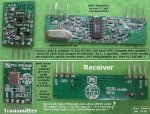
So it seems that what you may be receiving is just 'good old fashioned data corruption' which should be expected.
 

kd5crs

Senior Member
Ok, that makes sense. So the reason the U's aren't affected is that they are just on/off/on/off etc, so even if they pick up part of another byte they will still read as U?

I added a U between the GG and the first letter, so now the command is

GGUAUBU

I figured that since it can tell where U stops, that would help it find the A. So far, I'm 10 for 10 on successful transmits.

All hail the almighty U, solution to all wireless problems!

Thanks hippy.

Brian
 

kd5crs

Senior Member
Ok, never mind, it is like it knows when I post. Now I'm back to about the same success rate, still getting the Ps.

Maybe I should make all my commands a series of U's and G's? Those are the ones that reliably get through.

I could set up a receiver unit hooked by wire to the transmitter, that would compare what comes in over the wire to what comes in wirelessly. It would then repeat if they two don't match. That would be a major bandaid of a solution, though.

Any other suggestions?

Brian
 

hippy

Ex-Staff (retired)
I figured that since it can tell where U stops, that would help it find the A. So far, I'm 10 for 10 on successful transmits.
Technically "U" is the worse thing to send as it provides multiple false start bits if the SERIN has lost synchronisation. $FF ( for Nxxxx ) or $00 ( for Txxxx ) would likely be better.

That this appears to have solved the problem may just be coincidence.
 

sages

Member
Technically "U" is the worse thing to send as it provides multiple false start bits if the SERIN has lost synchronisation. $FF ( for Nxxxx ) or $00 ( for Txxxx ) would likely be better.

That this appears to have solved the problem may just be coincidence.
the problem is that you are trying to sync on the UUUU sequence which is only there to allow the rx bit slice to settle, it isn't a unique bit sequence needed to sync the rx uart.

Here's some example code I've written ( a couple of years ago ;) ) in 'C'.
http://www.sages.com.au/files/rfmodem.c
Note the tx routine and the pause after the 'U' sequence, followed by the actual data packet.
ie UUUUUUUU pause 55AAdata
the initial U sequence, the pause and the data preamble (55AA) is all needed.
there are comments in the code.
Whilst I haven't had a need for low level RF coms for a few years now, this code and technique has ( and is ) working in a lot of industrial applications out there.
hope this helps.
rod

[edit]
some pseudo code ( note syntax is a bit iffy :) )
pseudo code.
tx:
serout "UUUUUU"
delay 9mS ( approx 2 character times at 2400bps, ie 1 start, 8 bit and 1 stop )
serout 0x55,0xaa,data


rx:
serin 7,T2400,(0x55,0xaa), data

the 0x55,0xaa value isn't crucial but it is a unique bit balanced sequence.
 
Last edited:

kd5crs

Senior Member
I replaced the U's with $FF, which is all 11111111, correct? I added $00s at the end for balancing. So now it is:

serout transmit,N1200_8,("GG",$FF,"A",$FF,"B",$00,$00)

30 for 30 and counting.

So I guess the $FF works for my case because all the capital letters start with 0 (A is 01000001), so it can always sync on that first 0? Nifty.

Brian
 

sages

Member
there isn't a 1 and 0 policeman out there who is going to give you a ticket if they don't even out :D
the trailing '0' aren't achieving anything.
 

kd5crs

Senior Member
there isn't a 1 and 0 policeman out there who is going to give you a ticket if they don't even out :D
the trailing '0' aren't achieving anything.
I actually don't know if they are helping or not, but it works so I'm going to leave them in. I don't want the bit balance to bite me in the butt.

Also, this rock I have may not actually keep away tigers, but I'm not going to take the chance. :)

Brian
 

hippy

Ex-Staff (retired)
I figured that since it can tell where U stops, that would help it find the A. So far, I'm 10 for 10 on successful transmits.
Thinking further on this - Are you really getting better data reliability or are you just getting better corrupt data rejection ?

Are you really getting 10 out of 10 packets sent or are you getting 10 out of 10 non-corrupt data with some corrupt data rejected ?
 

moxhamj

New Member
There are too many things going wrong here for this to be a balancing issue. This sounds far more like an unreliable wireless link issue, probably with interference. Heck, it could even be the antenna wire waving around randomly.

First thing I did when confronted with this is to add a checksum and simply ignore packets that didn't add properly. Send a packet every second and flash a led when a valid packet with valid checksum arrives, and you mostly get a flash every second. Then go for a walk and see when it starts getting unreliable.

At least that way you won't have stray packets opening the doors to the airlock accidentally.

Next, set up a square wave on the Tx and scope the Rx. I'll bet the tops of the squares start rolling off at a much shorter distance than the rated Tx distance. That will be your extra bits creeping in and changing the ascii character.

But I got sick of the unreliability, especially when resending data clogs up the airwaves more and more. Wireless 'transceiver' modules are so much easier to work with.
 

Dippy

Moderator
It's always difficult to diagnose when we can't see the person's setup.
Physical setup, supply quality, antenna, hairy breadboards... they can all play a part in upsetting a link. And, as DrAc says, interference and things flapping around.

He's right, a 'transparent' transceiver can make life much easier.
But, it's only doing something that can, potentially, be achieved by you.
There's no such thing as magic.

I like sages' way of thinking.
All this onny-offy and balancing and timing is there to keep a) the receiver electronics happy and b) make it easier for your Serin to get started.

Many people are having great success with a simple preample and brief delay, e.g "U" or 0xaa and delay.
There is some useful Application stuff on the Radiometrix site.

If you are still having trouble it really would help if you posted:
1. Your schematic.
2. A picture of your setup.
3. Images of data sent and received.
4. Your latest test code.
 

sages

Member
the problem isn't a balancing issue of a magic even one and zero count.
it's that there is multiple factors to consider.

in an idle state ( ie no rx signal ) there is noise coming out of the rx and going into the bit slicer and appearing as digital garbage into the uart ( serial input code ). so if we try and decode any of this we will get garbage rx data.

next problem is we want to allow the rx cct to settle into a nice steady state allowing the bit slicer to have it's best chance of producing a nice clean digital signal. this signal should have ( for a 101010101010 input pattern ) a 50/50 duty cycle. if it doesn't then our ones may be smaller than our zeros or vis versa :) this is where the 'balancing' of the data can have an impact on what we decode. but as long as it is a fair spread and the message isn't extremely long then pretty much anything we send in a small application is going to be ok.

now we are at the sgate where our rx and data slicers are working at the optimum point. but! our poor little uart ( serial input ) is relying on having a nicely framed data stream to decode. to do this for asyncronous data ( which is what we are doing ) we need a start bit, some data ( 8 bit ) and a stop bit. a start bit looks exactly the same as any other '0' bit so we need something else to allow the uart to find a real start bit. if we send a '1' for more than two character period then the uart will be easily able to find our next start bit.

so:

1st we get '$%$%^$^%$%$$&%$' garbage
then we get @#$UUUUUUUUUUZ ( notice the garbage at the start and different character at the end. because the uart has probably sync'd on a '0' instead of a start bit.
then we wait for longer than two character times ............
and then we start sending our data packet ( with a unique character sequence so we can find it and don't get confused by the garbage when there is no signal ).

we need the start bit for the uart to decode our data properly and the only thing that can allow that to happen is a period of time longer than a full character time ( i use two character times but theoretically it can be 11 bit times ).

this would probably be easier to explain with some pictures but that's going to be a little work. i'll what i can dig up.
 

kd5crs

Senior Member
Thinking further on this - Are you really getting better data reliability or are you just getting better corrupt data rejection ?

Are you really getting 10 out of 10 packets sent or are you getting 10 out of 10 non-corrupt data with some corrupt data rejected ?
Well, I have a button on a unit with a wireless transmitter. When I press this button, the (wireless receiver) window blinds close. When I press this other button, the (wireless receiver) window blinds open.

With the most recent string I posted above, 100% of the time I push the button the window blinds open, and 100% of the time I push the other button the window blinds close.

So, I'd call it getting better data reliability.

I think all this stuff about bit balancing and antennas and whatnot that I've been posting has actually been distracting me from the real issue, which was that I was not receiving what I intended to receive due to the serial communication not syncing up.

I've tested it 50 more times since my last post, with 50 successes. So that's 80 so far.

So for anyone reading this at a later date, the information to take away from my experience using cheap 434 mhz transmitter/receiver pairs:

1. Use Wolfgang's U and pause preamble prior to each transmission.
2. Visually verify that you are receiving what you transmit by using the Picaxe programmer serial window. That will reveal if your A's are actually P's, for example.
3. $FF works well to separate capitol letters, which all start their byte with a 0.
4. Range issues aside (<50 feet) and unless you are in an extremely noisy environment, you should get very good results using these trans/rec pairs.

Thanks everyone!
Brian
 

hippy

Ex-Staff (retired)
3. $FF works well to separate capitol letters, which all start their byte with a 0.
To be pedantic, they don't; they end with a 0 when sent serially and that 0 is sent as a high for Nxxx baud rates. What it can do is give the SERIN a bit of a breather, similar to the pause after the "U" preamble so it has a better chance to sync up with the start bit which is the first thing it will see next.

But anyway, it seems to be working reliably now and that's the important thing.
 

manuka

Senior Member
Bravo on the great insights guys. I've been wrestling alligators recently, & my Forum attention has lapsed. These workarounds look very beneficial & perhaps merit promotion - maybe an Instructable in Dr_A's style ?

Those links mentioned are marvellous! Effectively they say that in the absence of a strong signal,an ASK receiver's Automatic Gain Control (AGC) increases the gain until there is a near constant output of random noise. Sending significant "wakeup" alerts effectively raises the sensitivity threshold,thereby improving the signal to noise (S/N) ratio. FSK (Frequency Shift Keying) has better noise immunity of course, but such modules are more costly.

A myriad of dirt cheap & "deaf" 433 MHz data units abound, but these may become enormous time wasters.I've long recommended folks start simply but predictably with 433 MHz ,perhaps using the likes of the reliable Keymark ASK super-het. devices below (sold "down under" by Jaycar as ZW3100 & ZW3102). Their silkscreened ID on the module pins may alone help prevent confusion! My own 433/PICAXE experiences have usually been seamless,with few of the wireless woes near endlessly posted here. Interference issues,perhaps arising from cheapie super-regen receivers, in many cases seem a major culprit for others.For more ambitious work HopeRF/Yishi etc transceivers are of course recommended,while -yes- I too recommend Radiometrix for gold plated budgets & applications.

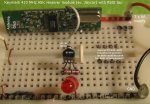
I've recently been probing a Keymark receiver & have pleasingly located an undocumented RSSI signal strength tap. This can conveniently be wired to a redundant module Gnd pin. RSSI output ranges from ~2V (no signal) to ~3V (strong nearby tx), & although it'll just drive an LED, it needs buffering for more "illuminating" insights. Stan.
 

Attachments

Last edited:

manuka

Senior Member
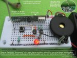
OK- it's fine work with a single PTH contact,but do-able. Simply run a thin wire from the Keymark RSSI tap to a BC548 NPN that drives a super bright red LED. Voila! As a bonus the setup even seems to run at voltages below the modules normal 5 ±½V data needs too. It readily picks up other very nearby 433 MHz units, & has already showed it's worth for both wireless doorbell TX battery & local "is my #%$@#$%& 433 MHz PICAXE Tx working" verification. Every UHF workroom should have one!

There are of course numerous ways to organise & process this RSSI output, but as I'd been asked to dream up a cost effective (~US$10) 433 MHz Rx for scout jamboree foxhunting, barebones simplicity is the essence. Hence this RSSI hack may suit the need- we could even name it "SCOUR" = "Stan's Crafty Outdoor UHF Receiver" to go with a companion "SCOUT" transmitter. Yeah- there's a tape measure based SCOUA Yagi antenna already developed.

Initial tinkering I've done has produced the reliable setup below, which draws ~10mA at ~ 4V. The little blighters performance is most satisfactory,& RSSI LED brightness nicely relates to signal strength as is,although considerable resistor & LED tweaking may suit others. Even slap in a few diodes to adjust threshold, or use other colour LEDs perhaps. Ranges to ~50m-100m with ~175mm whips on both TX & RX, but with a 6dB "cotanga Yagi" more like 100-200m even thru' light vegetation & wooden buildings. Direction finding impressive with the latter, but simple body shielding (or even antenna removal) can assist close in. Enjoy (& enhance?!) Stan
 

Attachments

Last edited:

Dippy

Moderator
Hey Stan, a man of your calibre would connect RSSI to an ADC and produce a bargraph.

I've found RSSI useful for.
1. Background survey.
2. Auto/adjustable squelch.
3. Interrupt to initiate Serial in.
4. Duty-cycle interrupt for low power receiver.

In fact I doubt if I would bother with a receiver which couldn't provide RSSI.
 

manuka

Senior Member
Thanks for feedback,& sorry if this is getting off the initial 0,1 thread. I've only a nodding interest, but ARDF (Amateur Radio Direction Finding) "Fox Hunting" is a dead serious competitive sport,especially in Eastern Europe & Asia (where it's long been part of schools PE/map reading programs). There's even talk of it being included in the Olympics. Frequencies are usually at 144 MHz or (now an almost DC!) 3.5 MHz. My quest here was for a general 433 MHz receiver & Scout Jamboree level "fox hunt" teaser that's EASILY CONSTRUCTED & usually WORKS,but is CHEAP (~US$10) & open to ENHANCEMENT.

FWIW I was rather taken back with that shunted 220 Ohm resistor, but that's how the initial setup best performed! OK on the LM3914, but such an approach may be as costly all up as a PICAXE. Sound,perhaps as a varying tone,may be a superior RSSI indication anyway-LEDs are power hungry & will be hard to see when running thru' bush & in bright sunlight of course too. All manner of noises are easy to rustle up with a PICAXE,with feed into cheap headphones. However there goes another US$3-$5 for a 08M & headphone socket... Stan.
 

Attachments

manuka

Senior Member
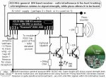
Sound it is Sir! However the cost & skills sensitive Scouts RDF project sadly doesn't look as if it'll stretch to a PICAXE. Sniff... Even field soldering may be off, as their Jamboree in October is essential outdoor. I've hence tinkered with the initial circuit (while also attempting to make it easier to construct as well),& used a cheap piezo to allow the signals (sourced from the data feed pin) to be heard. The RSSI tap itself ( ranging ~2- ~3 V but at low current) is now feeding a classic Hi-Z input Common Collector Emitter Follower to good effect. Circuit current drain all up ~5mA running from 4 x 1.2 V NiMH.

Walkabout performance has been most satisfactory, & even when 50m away (with buildings & light vegetation in the way too) from the simple TX the signal could readily be heard with just 175mm whips at both ends. Line of sight probably twice this, with a simple 6dB Yagi maybe even 200m. The piezo is not HiFi of course, but audio output was quite OK in both volume & tonal quality.

The RSSI allowed simple DF just by body shielding & triangulation. In fact I promptly identified & then located an unknown 433 signal when passing my garage. This turned out to be from a stored ~2007 vintage "Cent-a-meter" energy meter transmitter that had somehow turned itself on in the box. I'd have never known about it otherwise. I noted the reflecting metallic garage door showed peaks & troughs as the receiver was moved closer/further away from it. UHF antenna design & element peaking anyone?

Rest easy -PICAXE applications have not been forgotten- RSSI values change with obstacles (especially metallic) in the propagation path! This may suit detection of vehicles etc from some distance away by the changes in RSSI. Aha- now that's an idea. Stan. ZL2AJZ
 

Attachments

Last edited:

MFB

Senior Member
Off topic

Reminds me of a WW11 anti-aircraft proximity fuse that I once saw. It used a single acorn valve oscillator that’s frequency was pulled by metal objects in the proximity of the antenna circuit. The resultant change in valve current activated a relay and ignited the warhead. The whole circuit was potted in bees wax for protection when the shell was fired. Just think how many allied bees must have contributed to the war effort!
 

manuka

Senior Member
Aside from the A-bomb, proximity fuses are still considered THE most effective WW2 shortener. Many in the UK south enduring the 1944 V1 blitz owed their continuing existence to them also-barely 5% of these "buzz bomb" cruise missiles got past. The VT fuses were a marvel of VHF valve era constructional ruggedness & ingenuity - their battery alone was a masterpiece of lateral thinking.

According to Google -Technically the Allied fuse was not radar as it did NOT send out a pulse and listen for an echo. It had 4 tubes. One tube was part of the oscillator. When a 'target' that was about a ½ wavelength in size came within a few VHF wavelengths ( hence ~5-10 metres) it would load the amplifier and the anode current would increase. Two additional amplifiers would detect this change and then triggered the 4th valve (a gas filled thyraton) to set off the detonator.

Some PICAXE UHF "proximity" readings may be in order- stay tuned. Stan.

Dippy: My current antipodean range ~20,000 km - signals a tad weak...
 
Last edited:

manuka

Senior Member
Quick test- ~30m from street thru' light vegetation & surburban property to indoor receiver. Simple ~175mm whip antenna both ends.

Metal garage door shut gave steady 2.14 V RSSI, rising to 2.28 V when door wide open.
A 2nd indoor trial had no signal 1.95V,but with TX ~5m away across room this rose to ~2.48V

I've further modified the circuit above with a ~1 Meg resistor from the RSSI tap to GND- this gives a handy squelch feature when in circuit. Listening to white noise is painful ...
 
Last edited:
Top