FSK Modulator using 14M

MFB

Senior Member
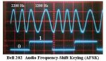
When transmitting data over an audio link there are many advantages in using frequency modulating. Modem chips that can operate over audio bandwidths are becoming harder to source and more expensive but (if you can find them) they provide excellent performance, at typical data rates of 300-2400bps. However for applications that are able to use a lower data rate, the following PICAXE generated FSK modulation technique might be of interest.

The attached schematic shows a 14M that produces an eight-segment waveform that, with the addition of a low-pass capacitor, provides an approximation of a sign wave. This has the advantage, over a square wave, of producing less troublesome harmonics. The example code below produces a constant frequency of 550Hz (8MHz clock). One way to add modulation is to place an if..Then pause command between each new DAC value, which can modulate the frequency depending on the status of an input pin. This extra code does of course reduce the maximum frequency. For example, using a pause value of 2 gives requires of 265Hz and 143Hz, which is able to support a maximum data rate of about 50Hz (maybe Stan could recommend some free software to decode these signals with a PC sound card). Faster PICAXE chips could produce proportionately higher frequencies/data rates.

The PICAXE is of course fully committed whilst generating FSK modulation and is unable to perform other tasks. However, for many low-speed telemetry applications, it would still be possible to alternate between measuring input parameters and transmitting data.


setfreq m8
main:
pins = 8
pins = 12
pins = 14
pins = 12
pins = 8
pins = 2
pins = 0
pins = 2
goto main
 

manuka

Senior Member
An interesting one MFB ( but the "main" program is missing)! Yes- there's diverse PC based decoding software around able to handle all manner of (A)FSK tones & freq. shifts. See => www.kc2rlm.info/soundcardpacket/, => www.scancat.com/SkySweep/generic_fsk_decoder.htm , => www.winradio.com/home/fskdecoder.htm etc.

At the encoding level, classic Bell 202 standard 1200/2200 AFSK ICs tend to be elusive & increasingly costly, so I've indeed pondered both PICAXE based AFSK & DTMF. Note that the transition from one frequency to the other has to occur in a manner that retains phase continuity- stop/start won't do! Tones don't need to be too pure for decoding, but the actual frequency is more crucial. Good old CALIBFREQs can even tweak this - much as VK6HV & I have recently done with 08M generated Hellschreiber.

I've got to say that DTMF (which maxes at ~ 10 ch.p.s) may have better slow data rate PICAXE appeal - even a sniff of it in the noisest links will usually be decoded OK. PICAXE based AFSK/DTMF remains one of my diverse back burner projects, although when answering the handy phone too rapidly (first ring!), lingering caller ID snatches keep nagging me to reconsider. Stan.
 

Attachments

Last edited:

moxhamj

New Member
Yes, the transition between frequencies must occur at a zero crossing otherwise high frequency harmonics are introduced.

I've pondered 1200 baud modems but I think at the 14M clock speeds it might be more a 1.2 baud modem!

The transmitting is relatively easy. Receiving is more complex. As manuka says, DTMF has appeal too, and the LM567 interfaced to a picaxe may be possible.

Then again, the decreasing cost of 433Mhz transceiver modules ($20 or less) and their ease of interface with picaxes makes these an attractive option.

For those that like a technical challenge, maybe it is possible to do it all in software. A fully committed Z80 might be able too, using sine lookup tables and log tables to do the squaring needed for fourier transforms. The attached document has some interesting background on the maths.

And maybe it could be done in raw PIC code.

Which brings up a question I've never really thought of till now - is it possible to mix-n-match picaxe basic and raw pic code in a single program?
 

Attachments

hippy

Ex-Staff (retired)
is it possible to mix-n-match picaxe basic and raw pic code in a single program?

No.
 

MFB

Senior Member
Many thanks for the comments and links.

Checking the input pin between each new DAC value does allow the frequency to be changed ‘on the fly’ in order to reduce harmonics. I have seen 4MHz PIC assembler code that outputs FSK at 1200bps whilst also reading ADC inputs under interrupts but can’t remember the link.

Rather than acting as a dedicated modulator, a PICAXE could alternately measure slowly changing analog inputs (temperature, pressure etc) and then output FSK modulated data. This would be suitable for use with narrow band audio channels like walkie-talkies and ‘bug’ type FM transmitters or, recording data on a video audio channel.
 

hippy

Ex-Staff (retired)
Direct Digital Synthesis is usually done by using a lookup table of the wave form ( often sine ) and stepping through the phase / angle of the waveform at various rates ...

phaseStep = 1
Do
phase = phase + phaseStep
Read phase, pins
Loop

That works but is slow; if 256 steps in the waveform and it takes 1ms per step, output at phaseStep=1 will have a waveform length of 256ms, a frequency of ~4Hz, with phaseStep=32 ( an 8 step waveform ), a length of 8ms, a frequency of 125Hz. Increase the operating speed and you correspondingly increase the available frequencies. If those results were attainable at 4MHz, at 64MHz the frequency output range would be 64Hz to 2kHz.
 

MFB

Senior Member
The attached scope shot shows FSK modulation (if...then pause command between each new DAC value) at about the maximum data rate. It seems like the Generic FSK Decoder software suggested by Stan for PC sound cards should be able to filter and decode these non-standard modulation frequencies. Alternativly, a PPL/level detector chip could be set up as a demodulator and I'll probably try this next.
 

manuka

Senior Member
Well this is certainly looking promising! But those low audio freqs you'd initially mentioned may be an issue with normal 300-3000 Hz audio passbands. Comms circuitry may render such low freq. 265/143 Hz tones sub-audible- a significant reason why ~1kHz is used for Morse, DTMF, Hellschreiber, & normal RTTY etc. I'm reminded of a shift to "off the top" higher AF tones a Luftwaffe WW2 beam bombing system employed. Tones then became "invisible" to the Allies, & only when the pass band was widened - some (tragic) time later- were they detected... (It's all in "Most Secret War" by R.V. Jones)

Consider giving PICAXE generated DTMF a scare? This has previously been Forum pondered using single & dual 08Ms => http://www.picaxeforum.co.uk/showthread.php?t=8140&highlight=dtmf . Audio tones can be CALIBFREQ etc tweaked to suit DTMF specs of course.
 
Last edited:

MFB

Senior Member
FSK at 110 baud?

To bring the tones within the normal audio passband it will be necessary to use an X1 or X2 PICAXE. At 16MHz the two tones will be 286 and 530Hz, which should support the standard data rate of 110 baud.

Good to hear that you’re also an R.V. Jones fan. I was fortunate enough to work (at Bristol University) with a couple of the people that he mentioned in the book.
 

moxhamj

New Member
Another R.V. Jones fan here.

Just pondering here, but the max baud rate of a 1200/2200 FSK would be one sine wave cycle per bit. And that needs DSP with a moving window and lots of summing of squares etc. Beyond a picaxe. BUT - what about a system that had more sine wave cycles per bit. Say you had 10 cycles per bit. Ok, the baud rate goes down. However, you can then use old-school bandpass filters (3rd/4th order?) to lock onto the frequencies (maybe tuned to do so over 5 cycles or so), then sample after a time delay corresponding to 10 cycles. Then feed the filter outputs into a picaxe.

Probably not practical. But fun to think about. I even was pondering a discrete component 16 sample bucket brigade device and op-amp multipliers to do the FFT...
 

MFB

Senior Member
Very slow demodulator

It’s certainly true that you need a dedicated demodulator chip or, a PC with sound card etc, to extract the maximum data rate for a given FSK bandwidth. However, if you don’t mind using many cycles to denote a mark/space, demodulation can be as simple as having RC high and a low-pass filters that cross over mid-way between the two frequencies. The output from one filter is rectified and fed to the noninverting input of an opamp, whilst the output from the other filter is fed to the inverting input. The demodulated digital output from the opamp will be compatible with a PICAXE digital input, providing a rail-rail amp is used and powered from the same supply.
 

AllyCat

Senior Member
One way to add modulation is to place an if..Then pause command between each new DAC value, which can modulate the frequency depending on the status of an input pin. This extra code does of course reduce the maximum frequency.
Hi,

Since this topic has been recently quoted in this thread in 2013 it might be worth commenting that the following code is not as daft as it looks:
Code:
#picaxe 20M2
symbol delay = b2
	if delay = 1 then goto nextline
nextline:
;  Continue
With M2 devices the execution time of jumps appears to have significantly increased over previous PICaxe chips, so the "true" path takes longer to execute than the "false" (fall through) path, so there may be no need to add a PAUSE at all. Also, note that PAUSEUS with low numerical values takes very much longer than "expected" .

Cheers, Alan.
 

MFB

Senior Member
Not sure how this old post popped up again, as all I did was include a link to it whilst replying to a current thread?
 
Top