An example on using the LIS302DL Accelerometer with PICAXE
Hello all,
I want to share what I have learned on how to use the LIS302DL 3-axis accelerometer breakout board. It’s a pretty cool sensor with I2C or SPI interfacing. You can buy it from SparkFun who make the breakout board or from cool components who stock it in the UK. Cool components deliver like lightening if you are in the UK, you could have one of these sensors in your hands and working within 1 working day of ordering and for under £25. For anyone who wants to add “tilt sensing” to your projects the LIS302DL is a good choice.
I make it sound easy to use, and it is, but for me it was not the case. I must have spent two days reading the datasheet over and over trying to extract useful information, and trawling the web trying to find any information on how to use it. I did not find any PICAXE related information on the unit but I found some AVR and PIC code written in C which I read and reworked into PICAXE code. So hopefully someone will find this information useful and save them some time getting up and running with this little unit.
Here is a list of all the documentation that I found useful:
Datasheet
Breakout Schematic
Application notes
I2C datasheet
Here is my example code that simply outputs the data to a debug screen.
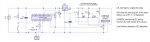
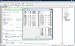
I have also attached my schematic and a print screen of the debug output. As you can see the debug screen shows a reading of 991mg or aprox 1g on the Z axis, which is what you wold expect as its axis is pointed towards the centre of the Earth. The sign byte is showing that the X and Y axis are both reading negative acceleration and of course Z is positive. With the averaging the noise on the readings is around +/- 10mg which is not bad.
I hope this helps someone out. It really is very easy to use and with PICAXE's built in I2C procedures it's a perfect match.
Huss
Hello all,
I want to share what I have learned on how to use the LIS302DL 3-axis accelerometer breakout board. It’s a pretty cool sensor with I2C or SPI interfacing. You can buy it from SparkFun who make the breakout board or from cool components who stock it in the UK. Cool components deliver like lightening if you are in the UK, you could have one of these sensors in your hands and working within 1 working day of ordering and for under £25. For anyone who wants to add “tilt sensing” to your projects the LIS302DL is a good choice.
I make it sound easy to use, and it is, but for me it was not the case. I must have spent two days reading the datasheet over and over trying to extract useful information, and trawling the web trying to find any information on how to use it. I did not find any PICAXE related information on the unit but I found some AVR and PIC code written in C which I read and reworked into PICAXE code. So hopefully someone will find this information useful and save them some time getting up and running with this little unit.
Here is a list of all the documentation that I found useful:
Datasheet
Breakout Schematic
Application notes
I2C datasheet
- To set up the circuit you need a level shifter because the accelerometer runs on 3.3V and PICAXE on 5V (if you can run the PICAXE at a lower voltage then I would guess you would be ok). Details on the level shifter are on p43 18.1 on the I2C datasheet.
- Once the circuit is set up you can begin to communicate with the module, I am using I2C. Its default is 100 KHz i.e. i2cslow.
- Find the slave address according to p19 5.1.1 of the datasheet
- Your first communication should be to initialise the module. Write to CTRL_REG1 (20h) to disable power down mode and enable the axis for use. Register details are from p24 of the datasheet.
- There is a register called WHO_AM_I (0Fh), which has constant value and can be read at any point and used as a sort of sanity check.
- So now to begin taking data from the module, we will be monitoring the STATUS_REG (27h) and the ZYXDA Bit, when this Bit=1 new data is ready.
- We can then access the OUT_X/Y/Z registers and read their values. The thing to note here is that the data is stored as two’s complement because acceleration can be negative. PICAXE does not support two’s complement or negative numbers, so you need to make up some kind of procedure to deal with it. Hopefully my method is clear from the code, but all I did is use the fact that if the number is more than 127 then it’s negative and subtracting it from 256 will give me the UNSIGNED number. I then used a variable to signal if it was a negative or positive output. I’m sure that there is a better method than mine out there to cope with two’s complement using PICAXE.
- So once you have the numbers you need to multiply it by the sensitivity of the device which is 18mg default (g as in gravitational force). The sensitivity is what each unit equals, so reading positive 10 from the X output means 10*18 = 180mg acceleration. See the application notes p32.
- So that’s reading the data sorted, but the output is not very steady so I average it over 10 cycles.
- You now have X, Y and Z data at your disposal! There are plenty of posts on forums online on how to use that data to calculate orientation if that is your aim.
Here is my example code that simply outputs the data to a debug screen.
Code:
'*************************************************
'**LIS302DL Example Program uisng I2C for PICAXE**
'**By Hussam EL-Sheikh (c) 6th July 2009**********
'*************************************************

symbol who = b0	'who am I
symbol dat = b1	'data ready

symbol X= w1

symbol Y= w2

symbol Z= w3

symbol TEMP = w4		'for use in calculations
symbol sign = b10		'sign byte
symbol ii = b11		'counter

let ii = 0
let X = 0
let Y = 0
let Z = 0
let sign = %00000000	'This is the sign byte, this is how it works: Bit0 is for the X axis
											  'Bit1 is for the Y axis
											  'Bit2 is for the Z axis
				'When the respective Bit is = 1 then the reading is negative


init:
   hi2csetup i2cmaster, $39, i2cslow, i2cbyte	'set up the I2C protocol for the LIS302DL
   hi2cout $20, (%01000111)	'Diable power down and enable X,Y,Z axis
   pause 10

data_check:
   hi2cin $27,(dat)		'Check if new data is ready
   dat = dat | %11110111	'isolate the ZYXDA bit with bit operation
   pause 10
   if dat = 255 then goto read_data
   goto data_check


read_data:
   hi2cin $0F,(who) 'Read who_am_i register sanity check should equal %00111011 or $3B

   '*************************
   hi2cin $29,(TEMP)		'Read X
   if TEMP > 127 then		'if it's negative remove the sign and raise a marker
   	 TEMP = 256 - TEMP
   	 TEMP = TEMP*18
   	 X = X + TEMP
   	 sign = sign | %00000001	'Bit operation to signal it's negative
   else
   	 TEMP = TEMP*18
   	 X = X + TEMP
   	 sign = sign &/ %00000001	'Bit operation to clear negative signal
   endif
  '**************************
   hi2cin $2B,(TEMP)		'Read Y
   if TEMP > 127 then		'if it's negative remove the sign and raise a marker
   	 TEMP = 256 - TEMP
   	 TEMP = TEMP*18
   	 Y = Y + TEMP
   	 sign = sign | %00000010	'Bit operation to signal it's negative
   else
   	TEMP = TEMP*18
   	Y = Y + TEMP
   	sign = sign &/ %00000010	'Bit operation to clear negative signal
   endif
   '*************************
   hi2cin $2D,(TEMP)    	'Read Z
   if TEMP > 127 then		'if it's negative remove the sign and raise a marker
   	 TEMP = 256 - TEMP
   	 TEMP = TEMP*18
   	 Z = Z + TEMP
   	 sign = sign | %00000100	'Bit operation to signal it's negative
   else
   	TEMP = TEMP*18
   	Z = Z + TEMP
   	sign = sign &/ %00000100	'Bit operation to clear negative signal
   endif
   ii = ii+1

'***************************
   if ii = 10 then			'Take an average over 10 cycles

   	ii = 0
   	X = X/10
   	Y = Y/10
   	Z = Z/10
	debug
	X = 0
	Y = 0
	Z = 0
   endif

goto data_check
I hope this helps someone out. It really is very easy to use and with PICAXE's built in I2C procedures it's a perfect match.
Huss
Attachments
-
 42.4 KB Views: 133
 -
 175.1 KB Views: 94
Last edited: