Picaxe controlled battery discharger

Andrew Cowan

Senior Member
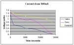
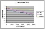
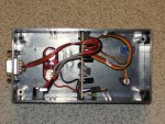
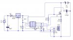
I built this as a simple battery discharger recently. A friend wrote some software to draw voltage/time graphs based on incomming data.

It uses a FET driven by an analogue voltage to maintain a constant discharge current.

The current is monitered by a 0.33 ohm (1 watt) shunt resistor.

The unit is designed to discharge AA batteries (1.5V) at 500mA or 50mA, selectable by a switch.

Code:
init:
setfreq m8
symbol desiredcurrent = w0
symbol actualcurrent = w1
symbol pwmoutput = w2
symbol actualvoltage = w3
symbol convertedvoltage = w4
symbol convertedcurrent = w5
pwmoutput=0


main:
desiredcurrent = 50 'mA (14.5mA min).  Enter low value here.
if pin3=0 then
desiredcurrent = 500 'mA.  Enter high value here.
endif

readadc10 1,actualcurrent
readadc10 4,actualvoltage

convertedvoltage = actualvoltage * 100 / 21
convertedcurrent = actualcurrent * 145 / 10

if convertedcurrent < desiredcurrent then
	pwmoutput = pwmoutput + 1 MAX 400
	endif
if convertedcurrent > desiredcurrent then
	pwmoutput = pwmoutput - 1 MIN 400-400
	endif

pwmout 2 , 99, pwmoutput

sertxd ("I",#convertedcurrent,"V",#convertedvoltage,cr,lf)

goto main
A voltage regulator provides constant voltage to maintain calibration.

The LED in the box is on the serout pin, to show when the 08M is sending data.

Andrew
 

Attachments

Last edited:

BeanieBots

Moderator
Hmm, interesting.
You didn't find any issues with syncronising the readadc for current with the PWM drive pulses then or have you left the filtering off the diagram?
 

lbenson

Senior Member
Nice project. Was this to test the amp-hour ratings of various makes of batteries? What did your results show?
 

Andrew Cowan

Senior Member
There is a 10K resistor on the output of the 08M (not shown in the schematic). This then leads to the FET gate and 0.47uF capacitor (which is shown). These seem to fully smooth the signal.

This was a school project, and we tested three battery types - Duracell Ultra, Sony Plus, and Varta Longlife.

It would be nice to calculate the area under the graph (and thus capacity), but my software guy didn't know how to do that. The attached graphs are made in excel, the graphs made by the software were a little strange to look at.

The batteries performed as expected - more expensive is better, but in the low current drain test, we found that the Sony batteries were only slightly better than the Vartas, while being more than twice as expensive.

A
 

Attachments

Last edited:

BeanieBots

Moderator
Yes, I thought you'd simply forgot to put it on the diagram.

EDIT:
You got just over half what I get for a Duracell Ultra.
 
Last edited:

wlie

Member
Andrew Cowan

I tried to build your "Picaxe controlled battery discharger" but I can't get it to work.
It might be because of a wrong FET. I have used a IFR520 and it looks like it doesn't conduct (no current).
Please tell me what type are the Q1 in your schematic?
 

Andrew Cowan

Senior Member
I used an IRF530, but the IRF520 has the same pinout and should work. Can you post a photo of your circuit so I can try to see what is wrong?

You should have 5v on the gate of the FET, and the FET should have a resistance of a couple of ohms.

Andrew
 
Last edited:

wlie

Member
Andrew

Too late for photo - I build it on a breadboard and it is dismounted now.
I will try it again sunday, measure the gate and if still problem I will take a picture.
What do you mean by "the FET should have a resistance of a couple of ohms"?
Do you mean R4 shown as 0,33 ohm? I didn't have this so I used a piece of Kanthalwire.
 

MPep

Senior Member
@AC,
Surely there should be a resistor in series with the D2 LED!! :D
A simple but effective project.

Did you mean Rdson? When you mentioned:
the FET should have a resistance of a couple of ohms.
@Wlie,
As long as the resistance comes to 0.33 Ohm, then you should be okay.
Unless you recalculate the measured voltage and adjust the program accordingly.

MPep.
 

Andrew Cowan

Senior Member
At thehighest discharge mode (500mA), the total resistance of the FET and R4 must be 3 ohms. This means that the Rds onn of the FET must be less than 2.7 ohms. While the datasheet for the IRF530 says this is milliohms, remember that it is not a logic level FET, so with a Vgs of 5 colts, the resistance will be around 1 or 2 ohms.

R4 does need to be 0.33 ohms, or the unit will not use he correct current (although you could recalibrate it).

A
 

wlie

Member
I think I found the error. It was not because I had built the circuit wrong, but because I didn't looked long enough at the ampmeter or the SERTXD readout.
The first few seconds there is no current flowing through the resistance, but after 5 to 10 seconds the current rises slowly after which it falls again.
Then rises and falls the current with a slow frequency (1 to 2 seconds). It looks like the circuit oscillates. Very strange behavior.
I have created and attached a drawing right after my breadboard, just to make sure that I have not misunderstood your schetch.
Your program are cut and paste onto the PICAXE, but as the readout are very quicly, I have made a small change so that I only have a readout for every 50 value.
Code:
#picaxe 08m
init:
setfreq m8
symbol desiredcurrent = w0
symbol actualcurrent = w1
symbol pwmoutput = w2
symbol actualvoltage = w3
symbol convertedvoltage = w4
symbol convertedcurrent = w5
pwmoutput=0


main:
desiredcurrent = 50 'mA (14.5mA min).  Enter low value here.
if pin3=0 then
desiredcurrent = 500 'mA.  Enter high value here.
endif

readadc10 4,actualcurrent
readadc10 1,actualvoltage

convertedvoltage = actualvoltage * 100 / 21
convertedcurrent = actualcurrent * 145 / 10

if convertedcurrent < desiredcurrent then
	pwmoutput = pwmoutput + 1 MAX 400
	endif
if convertedcurrent > desiredcurrent then
	pwmoutput = pwmoutput - 1 MIN 400-400
	endif

pwmout 2 , 99, pwmoutput

inc b13
if b13 = 50 then gosub readout

goto main

readout:
sertxd ("I = ",#convertedcurrent,"   V = ",#convertedvoltage,cr,lf)
let b8 = 0
return
Code:
I = 0   V = 1514
I = 0   V = 1523
I = 0   V = 1519
I = 0   V = 1533
I = 0   V = 1523
I = 0   V = 1523
I = 0   V = 1519
I = 0   V = 1509
I = 0   V = 1519
I = 0   V = 1514
I = 0   V = 1523
I = 406   V = 1333
I = 0   V = 1519
I = 0   V = 1519
I = 217   V = 1414
I = 0   V = 1519
I = 0   V = 1519
I = 101   V = 1466
I = 0   V = 1519
I = 0   V = 1519
I = 29   V = 1514
I = 0   V = 1519
I = 0   V = 1528
I = 0   V = 1500
I = 0   V = 1523
I = 0   V = 1633
I = 14   V = 1523
I = 0   V = 1519
I = 0   V = 1514
I = 0   V = 1528
I = 0   V = 1523
I = 0   V = 1523
I = 0   V = 1523
I = 0   V = 1523
I = 0   V = 1519
I = 0   V = 1519
I = 0   V = 1523
I = 377   V = 1338
I = 0   V = 1528
I = 0   V = 1519
I = 174   V = 1414
I = 0   V = 1514
I = 0   V = 1519
I = 72   V = 1471
I = 0   V = 1519
I = 0   V = 1519
I = 14   V = 1509
I = 0   V = 1514
I = 0   V = 1519
I = 0   V = 1523
I = 0   V = 1523
I = 29   V = 1509
I = 0   V = 1523
I = 0   V = 1523
I = 0   V = 1533
I = 0   V = 1523
I = 0   V = 1500
I = 0   V = 1519
I = 0   V = 1523
I = 0   V = 1523
I = 0   V = 1514
I = 0   V = 1523
I = 0   V = 1514
I = 319   V = 1361
I = 0   V = 1523
I = 0   V = 1519
I = 116   V = 1442
I = 0   V = 1523
I = 29   V = 1523
I = 29   V = 1495
I = 0   V = 1509
I = 0   V = 1519
I = 0   V = 1514
I = 0   V = 1514
I = 0   V = 1519
I = 0   V = 1514
I = 0   V = 1523
I = 0   V = 1519
I = 0   V = 1523
I = 0   V = 1519
I = 0   V = 1519
I = 0   V = 1523
I = 0   V = 1514
I = 14   V = 1519
I = 0   V = 1523
I = 0   V = 1528
I = 449   V = 1271
I = 0   V = 1523
I = 0   V = 1528
I = 246   V = 1395
I = 0   V = 1514
I = 0   V = 1519
I = 116   V = 1457
I = 0   V = 1519
I = 0   V = 1523
I = 14   V = 1490
I = 0   V = 1523
I = 0   V = 1519
I = 0   V = 1519
I = 14   V = 1514
I = 0   V = 1514
I = 0   V = 1519
I = 0   V = 1514
I = 0   V = 1523
I = 0   V = 1533
I = 0   V = 1519
I = 0   V = 1523
I = 0   V = 1519
I = 0   V = 1523
I = 0   V = 1519
I = 0   V = 1519
I = 0   V = 1514
I = 377   V = 1328
I = 0   V = 1538
I = 0   V = 1523
I = 174   V = 1423
I = 0   V = 1528
I = 0   V = 1528
I = 58   V = 1480
I = 0   V = 1523
I = 0   V = 1519
I = 0   V = 1504
I = 0   V = 1519
I = 0   V = 1523
I = 0   V = 1523
I = 0   V = 1523
I = 0   V = 1509
I = 0   V = 1519
I = 0   V = 1519
I = 0   V = 1523
I = 0   V = 1514
I = 0   V = 1509
I = 0   V = 1533
I = 0   V = 1523
I = 0   V = 1523
I = 0   V = 1519
I = 0   V = 1519
I = 0   V = 1519
I = 348   V = 1338
I = 0   V = 1519
I = 14   V = 1519
I = 174   V = 1423
I = 0   V = 1523
I = 0   V = 1533
I = 58   V = 1480
I = 0   V = 1523
I = 0   V = 1519
I = 14   V = 1514
I = 0   V = 1509
I = 0   V = 1528
I = 0   V = 1523
I = 0   V = 1528
I = 29   V = 1514
I = 0   V = 1519
I = 0   V = 1523
I = 0   V = 1519
I = 0   V = 1519
I = 0   V = 1523
I = 0   V = 1519
I = 0   V = 1523
I = 0   V = 1514
I = 0   V = 1519
I = 0   V = 1523
I = 0   V = 1514
I = 348   V = 1361
I = 0   V = 1509
I = 0   V = 1514
I = 174   V = 1438
I = 0   V = 1523
I = 0   V = 1514
I = 43   V = 1485
I = 0   V = 1523
I = 0   V = 1523
I = 0   V = 1509
I = 0   V = 1519
I = 29   V = 1514
I = 0   V = 1519
I = 0   V = 1514
I = 0   V = 1519
I = 0   V = 1519
I = 0   V = 1523
I = 14   V = 1519
I = 0   V = 1514
I = 0   V = 1519
I = 0   V = 1514
I = 0   V = 1523
I = 14   V = 1523
I = 449   V = 1295
I = 0   V = 1509
I = 0   V = 1523
I = 203   V = 1400

Any hint?

William
 

Attachments

BeanieBots

Moderator
Oscillation is very likely with an integral only control.
Ideally, you should add in some proportional but that is not easy when working close to the limit of the ADC resolution.

The only way I can think of doing it easily without major changes to the code would be to play with the overall time the loop takes to complete.

Try adding a pause (maybe 100 but do experiment) to slow down the response rate just after the pwmout command.
 

Andrew Cowan

Senior Member
That's odd - when I ran mine, I found that it took around 1 second for the current to rise, and then it would be fairly stable (+-5% or so). I'll dig my unit out and look at the results.

A
 

womai

Senior Member
If you need better ADC resolution, you may want to try the "pedestrian" ADC read that I posted recently:

http://www.picaxeforum.co.uk/showthread.php?t=13553

With it you should be able to use an external reference voltage applied to pin1 - just generate it with a suitable voltage divider. That will give 10 bits of resolution over a smaller range. To read a higher voltage just set the reference voltage back to VCC (5V).
 

BeanieBots

Moderator
@Andrew, it's the slow rise time of the current (caused by C1 0.47uF on the FET gate) that is the reason for the low frequency oscillation. Any system where control integral rate is greater than effect rate can't do anything except oscillate.
Either decrease the charge current delay (C1) OR decrease the loop rate. (put in a pause).

It's basic control theory. No getting around it.

Adding in womai's tip would be a good idea. Only needs two resistors and a few lines of code to significantly improve resolution and hence control.
 
Last edited:

wlie

Member
Found an error im my changed code.

Where I have written:
readout:
sertxd ("I = ",#convertedcurrent," V = ",#convertedvoltage,cr,lf)
let b8 = 0
return

It should be b13 instead of b8 - but that was only in this forum I have this mistake.

@BeanieBots
I have already tried with different pause without any change. Also tried with smaller capacitor (100nF) - only small effect on the frequency.
Unfortunately I don't have an Oscilloscope, it would have been nice.
 

BeanieBots

Moderator
Looking at your readout I see many are >1500.
Is that calibrated into volts. ie ~1.5v.
If yes, what are you charging? Maybe a dry cell or alkaline?
 

wlie

Member
I would not dare to charge a alkaline battery.
This program is not charging, it is discharging.
The figures shown are from discharging a alkaline batteri, but I have also tried rechargeable batteries.
 

BeanieBots

Moderator
Glad to hear it.
Not sure what made me think you were charging, I'll put it down to being over-worked;)
(the clue is in the title!)

If your battery is already quite flat, then a small change in current could have a large effect on voltage which might explain the large 'hunting' that you have seen.
Does it also oscillate when discharging a rechargeable type cell?
 

wlie

Member
Yes, the whole circuit seems very unstable no matter what type I try.

I don't know much about FET transistors and wonder whether it might have something to do with the very low voltage driving the FET. I have looked on the datasheet for the IRF520, but it doesn't tell me much.
Or it could have to do with the very low voltage the Picaxe 08m has to handle.

William
 

BeanieBots

Moderator
Both can/will have an effect on stability.
A sharp change in FET resistance for a small change in gate voltage will effectively make the loop very sensitive and lead to instability. Slowing down the loop should help but if combined with low resolution as well then some level of hunting will be enevitable.

You could try some potential divider action at the FET gate to reduce the overall system gain.
 

Duma

New Member
Are Pin 1 and 4 crossed between your schem and the prog?

pin 4 goes to + on the batt and pin 1 goes to the Q1-R4 combo.

to help with the debugging, add PWM to the output.
 

wlie

Member
@Duma
As I see it, PWMOUT and PWM are roughly doing the same, delivering some controlled pulses - no?
"Are Pin 1 and 4 crossed between your schem and the prog?" Looking at Andrew Cowans drawing, the number in the PICAXE-08M refer to Output and Input pins not physical pins.

@BeanieBots
I have tried putting in pauses with no effect.
"divider action at the FET gate"
It looks like a good idea, but I have no imagination how I can change the circuit without spoiling the effect of R4 C1. Any suggestions?
Maybe a change in the program could do the same effect?
 

BeanieBots

Moderator
I think you mean R5/C1.
As for "spoiling" the time constant, well.. that's the whole idea isn't it?
(and the programing method is to add a pause).

Anyway, if you want to maintain the same RC constant but reduce the gate drive, it works as follows:-

Let's say you have R1 into C1.
To make a potential divider, add in R2 between the R1.C1 junction and ground.
The time constant is now R1*R2/(R1+R2)*C1 (was R1*C1)
I'll leave you to do the rest of the algebra to back calculate as there are two unknowns and you must pick a value for one of the Rs before determining the other and/or adjust the value of C.

(If R1=R2 then using 2*R1 will give the same overall RC value)

As the threshhold voltage has changed, the original R.C becomes somewhat meaningless anyway.
It's overal loop response (including the battery characteristics) which matters, experiment!
 
Last edited:

wlie

Member
BeanieBots

Thanks for your help, I'll try to experiment with the hardware after your description.

For possible program changes, I didn't mean a pause but instead changing the duty cycle in the PWMOUT as this also should change the voltage on the FET gate.

William
 

Duma

New Member
Sorry typing too fast and not being clear on my questions.

1) add the PWM value to the out put string in order to monitor what is going on there.

2) "readadc10 1,actualvoltage" is taking a V reading from input 1 (pin 6 on the physical PIC). That line goes to the conection between the FET and the 0.33 ohm (1 watt) shunt resistor,(measuring the current flow thru the circuit.

3) "readadc10 4,actualcurrent" is taking a V reading from input 4 (pin 3 on the physical PIC). That line goes to the + terminal of the tested battery providing the actual vlotage of the battery.

am i right or just greatly confused.:rolleyes:
 

Andrew Cowan

Senior Member
Wow - you're right! (now changed). Looks like the code posted here was an earlier version than the version I was running!

Andrew
 

wlie

Member
I give op. Tried almost everything.
The circuit behave very strangely and I know apparently not enough about electronics or programming to figure out what is going on. Trying now to make a less sophisticated circuit.
Thanks to all who participated.
 

BeanieBots

Moderator
Seems a shame to give up this far down the line.
If you've gone to the effort of building the circuit and downloading a program to the PICAXE, you can't be far off.

Have you at least tried it with a well charged NiMh cell to eliminate issues such as rapid volt-drop that is likely to happen with a regular cell?
 

wlie

Member
@BeanieBots
Yes, I give up. I have spent a lot of time on it. Although it looks like a fairly simple circuit, I have unfortunately no imagination or knowledge enough to continue.

Mention it and I've tried it.
Brand new charged batteries as well as old and half discharged batteries (all MiMh). Also tried with new and old alkaline batteries.
Tried to build the entire circuit twice on breadboard with new components each time.
The only thing I can think of is that I have not tried to use an IRF530 which is what Andrew Cowan used. I have used IRF520, but according to datasheets, I can not see the big difference.
 
Top