Usage of I2C and SD21 (servo driver)

AndersNyman

New Member
Hi all!
I have some very basic questions about how to use the I2C bus and how to connect it to my picaxe 28X1 and SD21.
Im new to this things and will appreciate your help allot!

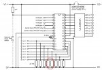
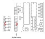
I have connect my parts like this (picture):


Is this right? Can I turn on the power?? :)

/Anders
 

westaust55

Moderator
Usage of I2C with AXE020 and SD21

Your connections are correct for i2c comms.

You will however need to remove the two 10k Ohm resistors which pull down the physical pins 14 and 15 as used for i2c comms.
I have circled these in the AXE020 schematic. This may be difficult as seems they are part of a SIL (Single in line) resistor pack.

Edit: You can also conenct to the header at the left side rather than directly top the PICAXE pins for the i2c comms at the AXE020 board. See second pic.
 

Attachments

Last edited:

nickpatts

Member
I think westaust55 means the two 10k resistors on the 28x1 project board not your two 4k7 resistors. this seems to be one of them resistor arrays (long black thing) on the 28x1 project board.
 
Last edited:

AndersNyman

New Member
Sorry, I mixed it all up.

So, it will work if I remove the 10k Ohm resistors (picture). But I need to connect new 10k ohm resistors to the other (0,1,2,5,6,7) inputs, if I want to use them?!


This is the latest schematic:
 

westaust55

Moderator
Yes the schematic is correct.

You will need to remove that in-line resistor pack you have circled.

Whether you need a resistor for a given input depends upon the device you are connecting.

Switches and LDRs for example will need a resistor of some value (10k is typical) but an input from another IC would not necessarily need a resistor.

If you have a multi meter and can work out which en of the resistor grid is the common (0V) terminal Will be at one end, then it may be possible to cut the resistor pack so that inputs 0,1 and 2 still have 10kOhm pull down resistors.

Internally the resistor pack will be like this:
Code:
   +-----+---+---+---+---+---+---+---+
   |     R   R   R   R   R   R   R   R 
   |     |   |   |   |   |   |   |   |
Comm

Looking at theAXE020 layout, the header conmector has the 0V pins at the bottom so there is every prospect the 0V / common lead for the resistor pack is at the bottom end (towards the reset switch).
 
Last edited:
Top