Measuring fuel level

wapo54001

Senior Member
I need a better way to measure fuel level in my gas tank.

Presently, I use a capacitive probe in a semi-clear plastic tank. It's a great system but has one drawback -- different gasoline mixes have different effects on the probe, so I have to re-calibrate the probe whenever I change gasoline types -- the two extremes being 100 octane low-lead on the one hand, and 87 octane with up to 15% alcohol on the other.

I'm wondering if there isn't some way to measure fuel level from *outside* of the tank, since the tank is translucent and non-metallic. Any thoughts very welcome.
 

westaust55

Moderator
Try a search on magnetostrictive transducers.

You could try using a float with a magnet inside the tank and then fix the magnetostrictive sensor to the outside of the tank.

If you can find a suitable unit it waould certainly avoid the issues of fuels with explosive atmospheres/ hazardous area implications
 

Dippy

Moderator
Lordy, I haven't heard that term used since my college/microwave days.

How will he measure the magnetostriction?
And the magnet/float movement would have to be very well controlled.

I was wondering if some kind of optical coupling method could be used or will the container material become stained over time? Or an accoustic resonance method?
Interesting project. There must surely be something on the nerdynet?
 

westaust55

Moderator
Some hydraulic ram suppliers use magnetostrictive sensors to monitor the the ram position. So far from ancient history.
 

Dippy

Moderator
Blooming cheek. 'tis only 18 years since college :)

You're going to wear Google out Westy.
How does it work?
I bet it is really easy (and cheap) for the PICAXE user ;)
 

westaust55

Moderator
No googling necessary (for me at least).
You will find I have made reference to them several times in the past on this forum.

Have used the mentioned hyd. rams on past projects. A magnet moves along a guide positioned by the moving portion of the ram. The sensors previously used incorporate all the necessary electronics in the transmitter pre-fixed to one end which provided a 4-20mA signal for distance which can be fed into a PLC.

Price is obviously higher than that of a PICAXE but less than a hydraulic ram. :)
Its all relative. . . . . I just spent AUD$20 :rolleyes: for a small resistor that goes in series with the ventilation fan motor in my old 4WD "truck" (Yeah = leaf spring in all 4 corners).
 

premelec

Senior Member
I'm wondering what electronics is doing in the hydraulic ram - I've always thought of them as a very simple pump with good reliability and no need for moving electrons - just a bit of liquid... and a good head... :)
 

jonphenry

New Member
I dont know what the cost of your probes are, but if your already familiar with capacitive probes, it would probably be best to just use another.

The capacitive measurement system is what we use in many military AC including the AC I maintained. The concept was simple, capacitance probes the length of the tank measured the level just like you already have. There were , however, more capacitive probes that were only a couple inches tall. They were meant to stay completely submerged. This way you can get a sort of reference reading to the makeup of the fuel. They were appropriately called compensation probes.

So, given you already have knowledge of the capacitance probe, I would say add another very short one for a reference reading and add it into your math.
 

Marcwolf

Senior Member
What about one of these ultrasonic measuring sensors that you see in robitic magazines?
I believe that they have a pretty good resolution.
It also depends on how much your fuel tank moves re the slop factor
 

BrendanP

Senior Member
I might be missing something here but why not use the same device that car and motorbike makers use? They're cheap and reliable.

Feed the signal form the fuel level sender into the ADC of the picaxe. I played around with one a while back, you may need to hook it up in a potential divider type arrangement. The resistance from the sender changes as the float moves up and down. Use a motorbike sender if its a really small tank. Use a hole saw to cut a hole into the top of the tank to mount sender.

Maybe its a REALLY small tank like on a RC aircraft, in that case this wouldn't work of course.

Its always worthwhile mentioning different stuff so if someone does a search and comes to the thread there's a variety of solutions.
 
Last edited:

Dippy

Moderator
I thought that Wap wanted to measure fluid level through the walls of a tank manufactured from a translucent plastic.
And that he didn't want a float or any wobbly thing.
And that he didn't want to penetrate the walls of the tank.
 

BrendanP

Senior Member
"....And that he didn't want a float or any wobbly thing.
And that he didn't want to penetrate the walls of the tank...."

Where does he explicitly say any of those things Dippy old son?

There's a very good reason why car/bike manufacturers all over the world use the float method, because it's cost effective and it works reliably.

Sure, it might not be a answer to this app for reasons that I am unaware of. But it is still worthwhile mentioning so others who come across this thread are made aware of it.

I see a lot of ideas get kicked around on the forum that I know will take massive amounts of time and effort to get to work reliably. Why bust a gut when there's a cheap (and safe) solution that will work with picaxe available off the shelf.

http://www.amazon.com/Moeller-Marine-Electric-Universal-Sending/dp/B000MTCRAA

http://www.rochestergauges.com/Pages/PDFs/8341_70.pdf
 

Dippy

Moderator
"I'm wondering if there isn't some way to measure fuel level from *outside* of the tank"
- post numero 1.

And he said the tank was translucent.

And if he wanted to penetrate the tank then a 50p float sensor would have been the obvious easy/simple/reliable answer , yes/no?

So, I assumed those criteria from what he said PLUS the fact that I assumed he didn't want to use the glaringly obvious i.e. a standard float level sensor.

I probably got it all wrong. I was just trying to pre-Nesbitise the thread :)
 

BrendanP

Senior Member
Glaringly obvious to you and I perhaps Dippy but I have no doubt there will be forum members/visitors unfamiliar with the humble fuel sender.
 

boriz

Senior Member
Just an idea.

Project a light into the tank illuminating the fluid. Maybe a vertical line of external optical sensors would be able to ‘see’ the glowing fluid through the translucent walls?

Here’s a little test I just performed using an old RC plane fuel tank and some water.

Normal light. You can just about see the water level. :


Same setup but with low ambient lighting and the fluid illuminated:


(AA Battery for scale)

Any colour light should work. Even Infra red. Modulating the light would help reject ambient effects. If this system could be made to work, it would have the advantages of being completely non-contact with no moving parts and safe in the presence of flammable vapours.
 

boriz

Senior Member
Another idea.

Could you weigh the tank? Maybe suspend the tank using stress gauges? Average the readings to eliminate ‘bounce’?
 

Ralpht

New Member
Pretty good ideas Boriz.

I would go for the strain gauge option myself. Weighing fuel and doing a bit of math is easy. Thats the way they do it in the aviation world. Weight of fuel in, engine fuel burn in pounds per min (or hour) , over burn time = fuel remaining.
Slightly simplified but thats what the big airliners do and sometime us little plane drivers as well. We don't trust fuel guages - we look to see exactly how much fuel is in the tanks. And we know how much fuel the engine burns per hour with great accuracy.

The light option may have some severe problems with reflected light and light leakages that may reduce accuracy. But having said that, a bit of tweaking the light sensors plus a bit of shielding might fix that problem
 

MikeGyver

Senior Member
lol you guys suck...
Freescale has liquid depth sensors. I think some GM vehicles have these sensors stock or something. When my friend taps into his truck's computer with his tuning program, it shows fuel with 1/10 gallon accuracy. It could just be the float though. I imagine you could simply tap a pressure sensor into the bottom of the tank. If you know the pressure (weight), and shape of the tank, you can calculate gallons or whatever.

Such as: http://www.freescale.com/files/sensors/doc/data_sheet/MPVZ5004G.pdf?fsrch=1&WT_TYPE=Data Sheets&WT_VENDOR=FREESCALE&WT_FILE_FORMAT=pdf&WT_ASSET=Documentation

If tank pressure poses a problem, you could probably use a dual port sensor and run a line from the top of the the tank to the back side of the diaphragm for reference.
 
Last edited:

wapo54001

Senior Member
Some fascinating ideas, and thinking outside the box. The one I like most is Boriz' idea of weighing the tank. That would require the tank to be free of any binding on the sides of the aluminum box that it rests in. I built the box, but can't remember how tight I made it, though I don't think the tank was "loose."

To clarify:

The float solution is indeed the least expensive. Many use it, but there are several problems with it.

You have to make a hole big enough in the top of the tank for the float to go through. That makes it a pretty big hole. Because the tank is flexible and since the top is not flat over enough area for a larger seal to work properly, these installations tend to leak. Also, these sensors are not very accurate. Also there is the question of positioning it so that there is room for the arm to make a full swing without obstruction.

Putting a shorter second capacitive sensor on the bottom is pretty much out of the question. The bottom is not flat and therefore very difficult to leak proof, and drilling holes in the bottom is considered to be very bad technique.

My current arrangement -- the capacitive probe -- is about 1/4" in diameter and drops through a press-tight rubber grommet in a 1/2" hole in top of the tank. Quite liquid proof as long as the tank is not held upside-down.


The light idea is the one I've been considering as most possible. A row of sensors up the side of the tank at one corner (which is rounded). If I shined the light through the bottom of the tank, would the light hitting a sensor above the liquid be substantially different than a sensor below the liquid line? Would the surface of the liquid work to reflect the light back down into the liquid? To visually verify operation, a colored LED would probably be better than IR. 100 octane low-lead is blue in color. Boriz' photos suggest the system might indeed work.
 
Last edited:

demonicpicaxeguy

Senior Member
you could always install two flow meters
1 for fuel entering the tank, and 1 for fuel leaving the tank, then simply count the pulses and minus the difference,
there shouldn't be much of an error considering it can be zero'd every time the tank gets filled
 

Dippy

Moderator
Sounds expensive DPG, and I don't think he wants to drill any more holes, but precise. I'm sure I've seen that method used somewhere...

I like the optical method too.

You raise some questions Wap, but aren't they 95% answered by that photo?

Why not try various colours - including UV (will fuel fluoresce? Mind you, maybe bad if the tank material does.).

To make it better, don't forget some coloured filter on your sensors.

One last thing: is there any chance the tank material will stain and affect your readings?
If so, then maybe using modulated light may help?
(...especially if ambient light varies.)
It sounds good fun.
Good luck.
 

westaust55

Moderator
The strain guage method mentioned by Boriz is good.
Ramsey Engineering used to make a device called C=Line (from memory) that you fixed strain gauges to the steel support legs of an existing tank and it gave a tank level - suitable for solids and liquids).

DPG's scheme is akin to one of the car computer kits. I installed one in a previous car and it had fuel flow sensors. Had to buy a second one for the return line for cars that had both supply and return lines from the engine.


@Wapo.
What is the application (full size car, model, other)?
What head room do you have above the tank? - The plastic water tank in my camper has around 100mm above it. My 125 litre 4WD fuel tank has around 75mm above it over most of the surface

Gems make a range of sensor devices. Here are links to a few:
1” NPT mounting Ultrasonic
http://www.gemssensors.com/content.aspx?id=5490

Float type level sensors:
http://www.gemssensors.com/content.aspx?id=2840
http://www.gemssensors.com/content.aspx?id=2846
 
Last edited:

Jeremy Leach

Senior Member
Ok, just wondering ...maybe just use software. You say your existing capacitive sensor doesn't give the same reading for different fuel types. BUT when your tank is full you've got a known quantity of fuel (well within a certain tolerance). If you get the software (via button press) to check the reading from the capacitive sensor when the tank is full, can't the software then just calibrate the readings ?

Actually, could even have intelligent software without the need for a button - if the reading has gone up (need tolerance to take account of natural variation in readings due to car position etc) then the tank has been filled - just need to make sure you fully fill tank for the software to work.
 
Last edited:

wapo54001

Senior Member
Ok, just wondering ...maybe just use software. You say your existing capacitive sensor doesn't give the same reading for different fuel types. BUT when your tank is full you've got a known quantity of fuel (well within a certain tolerance). If you get the software (via button press) to check the reading from the capacitive sensor when the tank is full, can't the software then just calibrate the readings ?
The calibration process for the probe requires a button push with 1 gallon, a button push with 5 gallons, and a button push at ten gallons. It is impractical to do every tankful.

Interesting idea, though -- I leave the probe calibration alone, but use an 08M to modify the output of the probe based on a switch position. I could have one position for 100LL and another for 87 with ethanol, and maybe a third one for "mixed." Certainly, that would be the simplest solution. I don't see how I could automate the process of choosing. Am I missing something?
 
Last edited:

Jeremy Leach

Senior Member
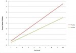
Not sure if you got my meaning 100%, apologies if you did. What I'm saying is: If you've got all fuel type A in your tank you will have a fixed, known FuelLevel/SensorVoltage graph - GraphA. If you've got all fuel type B then you will have GraphB. I'm imagining that GraphA will 'morph' into GraphB as you mix the two fuel types together.

So IF you fill the tank and press a switch (or the software detects the full tank), then the software should be able to 1) tell you the %age fuel mixture you've got in your tank and 2) determine the internal graph it needs to use to report the fuel level.

If you're saying that you wouldn't fill the tank to full then yep it won't work ;)
 
Last edited:

Dippy

Moderator
Therein lies the rub J. i.e. unless you fill it and press a button. Couldn't be automatic without some other switching as unknown fuel means machine doesn't know its full.

But a neat/slick approach.
 

Jeremy Leach

Senior Member
I would think that the software could know if the tank has just been filled, regardless of mix, just by comparing the present sensor value to the last. If there is a 'big' change in value then it would be safe to assume the tank has been filled up. I expect there will be some variation up and down in the sensor output anyway, so the software should only detect 'tank just filled up' for 'big' jumps of reading.

Once the software knows the tank has been filled then it can determine the mix/ graph.

Just an idea, and it seems a pity to go to the extreme of putting in new sensors etc when there's a perfectly good sensor already there and the software 'might' be able to handle the problem ;)
 

Attachments

Last edited:

Dippy

Moderator
Yes, but surely a 90% fill would be a "big jump" too. So would splashing? (Maybe code 'damping' will be needed too?)
But I agree with your theory. Real life is often different ;)
I don't know what accuracy is required.
Maybe your 'full' button would be easiest. A bit of wire and a cheap button.
 

wapo54001

Senior Member
Jeremy,

I did not understand you fully before, now I do, and I do like your ideas, but there are two problems I see:

1. Full automatic will not work because when power is removed to refuel, previous readings are lost. Thus, no way to recognize that a refueling has occurred without operator action (button press).

2. Press-to-calibrate button might work very well, provided two factors are true -- one, you always refuel close to "full" and, second, there is no momentary electrical loss to cause you to lose calibration with no way to recalibrate without refilling the tank and starting over. The inadvertent loss of calibration could get ugly.

I'm still leaning toward the 3-position switch to select calibration curves as the safest and simplest (already have the sensor probe).
 

Jeremy Leach

Senior Member
Hi there,

Remember there is EEPROM on picaxes, which does not lose its data even when power is cut.

The picaxe would determine the mix/graph only when the tank has been filled, and then save the setting into EEPROM, so it wouldn't be lost. It sounds doable to me, as long as the tank is always filled, and I don't think you'd need a button at all.

Am I right in thinking you get a voltage reading at the moment from your capacitive level sensor that you can read with a picaxe ADC input? If so, what does the graph look like for both fuel types?? I can then knock up some rough code to show you what I mean ?? ;)
 
Last edited:
Top