servo readadc help!

Hi guys,
servo and readadc problem!
first time Ive used this command. My futaba s3003 just arrived and Checked it works with the code from the manual. But I want to turn a pot, and for the servo to sort of follow accordingly, any help appreciated.
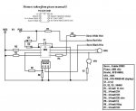
Using a 100k pot on input 0.

Code:
main:
servo 7, 75
readadc 0, b0
servopos 7,b0
goto main
 

BeanieBots

Moderator
You need to convert the POT number to one suitable for the servo.
Also, don't keep updating the servo command in the loop.

Try this:-

servo 7, 75
main:
readadc 0, b0
b0=b0 *10/17+75
servopos 7,b0
pause 25
goto main

EDIT:
100k not suitable. Use a 10k pot. (might get away with it)
 

BeanieBots

Moderator
The 75 to 225 range is only a guideline.
Most servos are only meant to do 90 deg sweep.
Play with the numbers to make it suit YOUR servo.

EDIT:
The ADC reading won't be very accurate with a 100k pot.
It's above the PIC recommended maximum input impedance for an analogue input.
 
Last edited:

Andrew Cowan

Senior Member
Currently you are getting readac values of 0 to 255 (if you have wired it up correctly).

using: b0=b0 *10/17+75

This equates to b0 equalling 75 to 225. This is the 'normal' safe values for a servo. Sending values outside this may mean the servo hits internal mechanical limits, damaging the servo. Have a play with the values, but if the servo won't turn any more, don't tell it to! If you turn it sloly by hand, you can feel where the limits are.

Andrew
 
Thanks BB and AC, got the full 180' now. rotated by hand and think its still within the limits - b0=b0 *10/16+50 . Hopefully not gonna blow my new toy!
 

Andrew Cowan

Senior Member
Thats odd - b0=b0*10/16+50 gives a servo range of 50 to 209. Although all servos are different, I'm surprised that it won't cope with values up to the standard 2225. But then again, maybe it is a slightly dodgy servo.

A
 
sorry been away for a while, cheers A
Yeah gonna play a bit more with it. Not sure what you mean with not being able to cope?

if it turns through 180'(dont necessarily need this, got no specific plans for its use yet) and there is 159 increments (209-50). Isnt this a good thing? Not sure i understand??

cheers Am
 

Andrew Cowan

Senior Member
Not sure what you mean with not being able to cope?
Most servos can only turn about 180 degrees before hitting their internal limits. If your servo turns 180 degrees between 50 to 209, it implies that with a input of 225, it would hit its limits. This is odd, as most rc speed controllers will happily give out a signal of 225.

A
 
Last edited:

212

Senior Member
This is very helpful to me too, I want to do the same thing...thanks!

I had already played with my Futaba 3003 servos and this is what I find with mine.


Main:

Servo 2 , 112 'move servo to center
Pause 1000
Servo 2 , 192 'move full counter clockwise
Pause 1000
Servo 2 , 112 'move servo to center
Pause 1000
Servo 2 , 34 'move servo full clockwise
Pause 1000
Low 2
Pause 3000
Goto Main
 
Last edited:

BeanieBots

Moderator
That's quite a large skew from 'ideal'.
Of the several dozen I've played with, none have been off by more than about 5, particularly on the ideal of 150 for center.

As long as the servo moves smoothly and NEVER hits the hard-stops, it should not be a problem.
 

Andrew Cowan

Senior Member
212 and or amateurman79 - do you have any other servos you could try? I have used S3003s, and they are usually withing 5 or 6 or the values they should be...

A
 

212

Senior Member
Tried an S3004 also, almost exactly the same??? Maybe this changes it though, I put a diode in the white wire so it doesn't feed back when I remove the power from the servo. I only power it to switch the nightshot on a video camera twice a day.... I don't move it that much, I was experimenting with it, and if I used much more than 192 or less than 34 it would hit the stop and just buzz. I don't think the diode was in there when I was playing, but I don't think it changed it either???
 

Andrew Cowan

Senior Member
The fact that it happens on two servos could mean something is not quite right with the timnings being given out - possibly the resonator is off by 10% or so.

A diode should cause noticible delay.

A
 

212

Senior Member
I'm wondering now, if the servos are different over there than over here??? Maybe someone knows for sure???
 

BeanieBots

Moderator
It's an international standard, so they should be the same.
You say you have a series diode in the signal:eek:
That won't help, it's a pulse, the pulse will charge whatever capacitance is on the servo input but not be able to discharge it. That will skew the waveform for sure. Try without the diode.
 

212

Senior Member
OK, I just tried with the S3004 using this circuit pictured. The only change in the code I posted was to put pin 4 high so the servo has power. I tried it as is, then with the diode jumpered...I can not see any difference????

No dippy, I bought the servos from a local hobby shop, not ebay :D
 

Attachments

Wrenow

Senior Member
First, I, too, question the diode. Second, you are turning the servo ground on and off. The pulse is a signal relative to ground. Are you connecting ground with enough time for the circuitry in the servo to stabilize prior to sending the pulse? I have never seen a servo with that much offset, either. This is a case where a scope or a digital servo tester like the ESky would be REALLY useful. http://www.helicopterfly.com/esky-ek20939-digital-servo-tester-p-1642.html
I have a couple of these, and they are a treat when diagnosing this type of issue - and you get a digital readout of your pulse stream (within servo friendly ranges).

Cheers,

Wreno
 

212

Senior Member
Here is what I tried it with tonight, the ground was on constantly. You are just up the trail a piece from me, I can send you a servo if you want to see what's going one with one. I have used three different servos and several different chips in the time I've played with them, and I thought maybe the manual example was for a different brand??? I'm taking this pretty far off topic I guess, but the info learned might be of some future use to others too.


Main:

high 4
Servo 2 , 112 'move servo to center
Pause 1000
Servo 2 , 192 'move full counter clockwise
Pause 1000
Servo 2 , 112 'move servo to center
Pause 1000
Servo 2 , 34 'move servo full clockwise
Pause 1000
Low 2
Pause 3000
Goto Main
 

Andrew Cowan

Senior Member
Have you tried connecting the black servo wire directly to ground? It shouldn't make any difference, but something funny seems to be going on...
A
 

BeanieBots

Moderator
R1 at 10R is rather high.
(that servo will pull ~1A when starting/stalled).

I have noticed with (some) servos that power supply voltage can effect position. Fortunately, it only has much effect below around 4.5v which is quite a handy feature. When you need to put in excess compensation, it's time to come in and charge your Rx batteries!

Can you try with a different 08M to eliminate PICAXE clock error.
Does shorting out R1 have any effect?

Infact, please just try it with 'normal' connections. No diode, no R1, no FET.
You can keep the 330R.

EDIT:
Actually, what is the purpose of R1?
If it is to limit current, reduce torque and/or slow down the servo, don't forget, it will also drop the volts to the control electronics. It would be better to put it in series with the motor and not the power supply.
 
Last edited:

Wrenow

Senior Member
I was also wondering about R1, and second BB's suggestion. I would try it per the normal hookup listed in the manual, no extra bits, no bits missing. That has always worked for me.

I have also sent you an email directly about a meeting of the NTXBG in the north Dallas area this Sunday. I can bring my servo tester if you are in the area and we may be able to see what is actually going on.

Cheers,

Wreno
 

212

Senior Member
R1 is in there because if the adjustment is off a little, the servo will slam the cameras nightshot switch real hard, and I don't like that. I THINK I did the tests with the normal hookup, and I know it was not with the circuit I posted here, but I will try it again. I'll try a couple of different 08Ms and with the two servos I have. Maybe the Picaxe needs it's own power too, I'll do that too. I have no complaints on how it works like I used it, but I'd sure like to know why it does what it does....thanks!
 

BeanieBots

Moderator
If it does what you want, then fine, leave it alone.

I'm quite sure R1 is to blame for the 'skew' and you should remove the diode for servo safety reasons.
If you say you want to reduce the torque to prevent "slamming", then move R1 inside the servo in series with the motor. Then the electronics voltage won't vary with load.
 
HI A,

sorry Ive been away. Tried with another servo but the same, probably my code. The servo command is different from what I use in the servopos command? Like I say Im just getting used to the picaxe! Anyhow playing with some IR code at the mo, to run the servo - not working, but will show the values Ive used - which started this thread. Probably a schoolboy error, and not worthy of the talented enquiries.

transmit -
Code:
let dirs = %00000101 ' switch pins 0,2 to outputs
main:
serout 2 ,N2400,(254,1)

readadc 1, b0 ' turn the pot, servo follows via ir
let b3 = b0/2  ' only 128 values available

serout 2,N2400,(#b3) ' show value on lcd
pause 1000

for b1 = 1 to 10  ' repeat send to make sure
infraout 1,b3
pause 45
next b1
goto main

receiver:
Code:
servo 7, 75
main:
b0 = 0 ' reset b0 - not sure if i need this
infrain2

b0 = infra * 2 'back to full 255

serout 2,N2400,(254,1) 
serout 2,N2400,(#b0)  '' show values on lcd - tried without this still doesnt turn servo
pause 250

b0=b0 *10/16+50  ' servo nb difference to top line

servopos 7,b0
pause 25

goto main
appreciate your time...simple servo explanation? or help with why servo doesnt turn. The lcd values match up either side of the ir

cheers
 

Andrew Cowan

Senior Member
Does it work if you change servopos to servo?

It will make the servo 'jump' a little every time it goes through it, but it may solve the pproblem.

Also try putting the LCD code after b0=b0 *10/16+50 and see what values you get there.

A
 

BeanieBots

Moderator
You should also take the LCD initialisation command out of the main loop.
It's only required once.
If it's purpose is re-alignment, then use 254,128 not 254,1
 
cheers guys - does work now but like andrew said, it jitters AND staggers its way to position. Any way to rectify that?
I took the B0 = 0 out to see if that would help but stopped working again, guess it needs to be there.

Doing a general search it seems people use 08m to wait for the signal then use the 18x etc for all other commands. Am i on the right lines? if so, how do you send the received signal to the 18x?? Not sure how to merge the two.
Would like it to run as smooth as possible - like it did (with your guys help) without Ir
Any help appreciated.
cheers AM
 

Wrenow

Senior Member
R1 is in there because if the adjustment is off a little, the servo will slam the cameras nightshot switch real hard, and I don't like that. I THINK I did the tests with the normal hookup, and I know it was not with the circuit I posted here, but I will try it again. I'll try a couple of different 08Ms and with the two servos I have. Maybe the Picaxe needs it's own power too, I'll do that too. I have no complaints on how it works like I used it, but I'd sure like to know why it does what it does....thanks!
Of course, tweaking the results and setting an end point should stop the over-reaching and slamming. A servo-saver (cushioned servo arm) can also reduce the ferocity of the "hit". Or a servo with less torque. Or a longer servo arm (increases speed a bit, but reduses the torque).

Another possibility is usinf an oblong shaped disk for the arm, resulting in a cam type action. We use servo horn disks coarve into cams (or screwed to a cam-shaped piece of wood or plasic) a lot o operate microswitches in Model Warship Combat. One use is putting a microswitch on either side of a servo such that turning one way operates one, the other operates the other. These are then wired into what is basically an H-bridge. Fives you full throttle forwards and reverse on higher amp motors - and was the common "throttle" before Electronic Speed Controls (ESC's became common and more reasonably priced (and factory waterproofed in some models now). They are called MAG throttles (for the Mid Atlantic Group innovators who came up with it). An article with diagrams, schematics, etc. is here:https://ntxbg.org/KnowledgeBase/?category_id=45&menuaction=phpbrain.uikb.view_article&art_id=13

In short, there are lots of ways to reduce the button pushing force other than reducing the power to the servo (especially before the electronics).

Cheers,

Wreno
 
Last edited:
hi A

LCD repeats the value over and over filling up the screen, range is from 05 to 208, but the servo stops (mechanical limits) before this is acieved. Might start over with the calibration. Still jutters, no where near the smoothness achieved without the IR, sometimes wants to be unresponsive, goes all the way back, b0 = 0???
might start over
 
Think your right, removed the serout commands, removed the lcd and works much better. Might re do the hardware use the chip to wait for the ir commands and use another chip for other functions. cheers Wrenow
 
Top