Best Stepper Motor Commands

mikemwa

Member
I just started on a project and I need a little help. I am pretty new to the picaxe micro controllers and the programming of them.
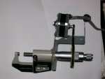
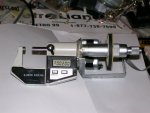
Basically what I’m doing is using a bipolar stepper motor to turn the handle on a micrometer to certain positions.
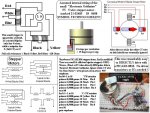
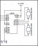
I am using a 20m and a MC3479 to drive the stepper motor.
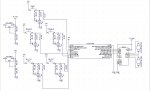
The first question I have is what commands are best for controlling the stepper motor? Below is what I’ve started with. It is something I just saw somewhere else and copied it.
I will have probably 6 push buttons and 6 led’s to come on when you push the buttons for forward fast, forward slow, reverse fast, reverse slow, start and beginning (which will probably be a later question).
Right now the pauses are in there just for testing. Ultimately what I want this thing to do is position the mic with the 4 position switches, hit the start button and the mic will move to a pre determined position, then wait for a signal and move to the next position etc.
Below is just the beginning of the code. I want to know if I’m going in the right direction.

Code:
'symbol revsl = pin0	'reverse motor slow
'symbol revfa = pin1	'reverse motor fast
'symbol forsl = pin2	'forward motor slow
'symbol forfa = pin3	'forward motor fast
'symbol start1 = pin4	'start sequence
'symbol begin = pin5	'move motor to start


'surface = 2			'take surface reading at .002
'minimum = 30		'take reading at minimum spec
'average = 33		'take reading .002 before average
				'then take 5 more readings .001 appart		
'maximum = 50		'take reading at maximum
'beginning = b4		'add upp all moves and move back that far to zero

start:
pause 3000

b2 = 5000		'stepmotor pause
b3 = 5000		'pause between steps

for b1=1 to 50
for b0=1 to 2 
pulsout 1,100:pause 2
next b0
next b1

pause 10000

for b1=1 to 50
for b0=1 to 28 
pulsout 1,100:pause 2
next b0
next b1

pause 10000

for b1=1 to 50
for b0=1 to 3 
pulsout 1,100:pause 2 
next b0
next b1

pause 10000

for b1=1 to 50
for b0=1 to 1 	
pulsout 1,100:pause 2
next b0
next b1

pause 10000

for b1=1 to 50
for b0=1 to 1 
pulsout 1,100:pause 2
next b0
next b1


pause 10000

for b1=1 to 50
for b0=1 to 1
pulsout 1,100:pause 2
next b0
next b1

pause 10000

for b1=1 to 50
for b0=1 to 1 
pulsout 1,100:pause 2
next b0
next b1

pause 10000

for b1=1 to 50
for b0=1 to 1
pulsout 1,100:pause 2
next b0
next b1

'goto start

'if pin0 = 1 then start
 
Last edited by a moderator:

hippy

Technical Support
Staff member
It may help to have a read of PICAXE Manual 3 - Interfacing Circuits where stepper motors are discussed. Start simple, then build up from there.
 

mikemwa

Member
Hippy, I have read the 3 manuals many times. I am also in the process of reading David Lincolns book.

Stan, I have that same motor and have worked with it. It's a nice motor to learn from. What I have now is a stepper out of a printer.

I can take care of most of the circuit myself. If I get stuck I will post questions then.

What I mostly need is help with the programming right now as I am learning making sure I use the best commands and the right structure.
Unfortunately, I work a full time and a part time job and I'm trying to cram all this in in between. Any help would be greatly appreciated.

Mike
 

BeanieBots

Moderator
I'd be looking at using the "pins=" command to set all output pins together and creating two subroutines for the movement.
One subroutine for each direction. Use a common variable for the number of steps to move.
It could still use the For/Next structure but Do/while might be better.
 

westaust55

Moderator
adding programme code within a post

mikemwa,

Can I suggest that you using the available forum commands to post your code in a sub window as requested in the sticky README post at the top of the Active forum.

Specifically:
If you add any PICAXE BASIC program code to your post, please enclose it within [code] [/code] tags e.g.
Code:
high 1
pause 1000
low 1
 

westaust55

Moderator
Stepper Motor control

The MC3479 stepper motor driver is considerable different in its interface to the PICAXE to a L293D.

You need to do a few of things before members will be better able to help you:

1. Draw up your proposed schematic showing how you intend to connect the MC3479 to the PICAXE,

2. Give a more step by step description of how you intend the control to work

3. Add some subroutine labels and comments to your program code so others have an idea on what each part is intended to do.

At the moment (and not worrying about the long pauses) your code just looks like 8 blocks of code in repetition sending out varying numbers of pulse
to the same output pin.


There is generally no alternative to most commands other than the loop structures as already mentioned. I suggest you aim to get it working and then fine tune the program code.
There may be a couple of ways to do some things - but they may not have the same time frames. For example:
You have used the PULSOUT command already but the other option is High x : PAUSE yyy : LOW x
PUSLE is more for short pulses (upto 65ms) whereas the other method is good for much longer pulses (1ms to 65 seconds)

But for now you need to provide more input as noted above.
 
Last edited:

mikemwa

Member
OK, I know how I need this to work now.

This will be attached to the handle of a Micrometer.

Using a Picaxe-20M and an L293D.
Bipolar stepper (200 steps per revolution) with a timing belt and pullys. 5 (on micrometer) to 1 (on motor) ratio. One rotation of the micrometer handle moves it .200 inch.

5 switches on inputs 1-5

1 = Forward slow to move 2-3 steps a second as long as the button is pushed.
2 = Forward fast to move much faster (whatever speed that might be) as long as the button is pushed.
3 = Reverse slow to move 2-3 steps a second as long as the button is pushed.
4 = Reverse fast to move much faster (whatever speed that might be) as long as the button is pushed.
5 = Start button. Push to start a sequence like thee following:

Use the buttons 1-4 to position the micrometer. Once in position hit the start button.

Move .002, Stop. Send signal to pushbutton. Wait for signal.
Move to .030. Stop. Send signal to pushbutton. Wait for signal.
Move to .033. Stop. Send signal to pushbutton. Wait for signal.
Move to .034. Stop. Send signal to pushbutton. Wait for signal.
Move to .035. Stop. Send signal to pushbutton. Wait for signal.
Move to .050. Stop. Send signal to pushbutton. Wait for signal.

Finished.

The signal and push button mentioned in the sequence will be coming off of another machine that this is attached to.

I hope this clears things up a bit as to what I'm trying to accomplish.
 
Last edited:

westaust55

Moderator
Stepper motor control - which driver IC

To make a decision on which IC you use:

1. You need to know the stepper motor current. For all intents I = V/R Amps

2. The MC3479 is rated at 18VDC max and to a max of 500 mA and a max of 350mA per phase/winding.

3. The L293D is rated at 36Vdc and to a max of 600 mA pre phase and a non-repetative peak of 1.2 Amps.

from a decision on which driver I then decisions on how to write the software can be made.

You will likely find more members of this forum with experience using the L293D but both should be relatively easy.
 

mikemwa

Member
OK, here's the proposed circuit for the project I'm working on. I'm sure there are a number of mistakes in it so let me know.
Everything I want this to do is in post #11.
The signal and push button mentioned in the sequence will be coming off of another machine that this is attached to. I have attached a Diptrace schematic file and a jpg file also.
 

Attachments

westaust55

Moderator
Have only looked at the schematic so far. Here as some comments:
Since you are using a PICAXE 20M, why not use the PICAXE pin identifiers to make it easy for others to review rather than the Microchip PIC pin references.


The 1 kOhm series resistors to the PICAXE inputs are not essential but no harm either.


The 330 Ohm resistor in series with each LED will allow around 12mA current to the LED.
You could use a 470 Ohm resistor in series dropping the current to around 8mA if power drain is deemed an issue.


For the LM317 Voltage Regulator, using the formula:
Vout = 1.25 * (1 + R2/R1)

The resistor combination for the 9V supply is right (R2 / R1 = 620 / 100 Ohms)
But for the 5V supply the calc only gives 3.75V with R2/R1 =200/100 Ohms).
Believe you will need 300 ohms instead of 200 ohms for 5V supply.


DATASHEET L293D DISCREPANCY TIME:

I note that for the L293D connections , while the Manual 3 page 17 shows both Vc and Vcc1 connecting to V2+,

On the CHI030 datasheet pin 16 connects to the same voltage as the PICAXE and only pin 8 connects to the motor supply voltage .

Oh for some consistency !

A VCC1 terminal, separate from VCC2, is provided for the logic inputs to minimize device power dissipation.

So I might suggest use the CHI030 connection scheme
 
Last edited:

mikemwa

Member
Thanks for the info.
I have only started using the Ditrace program to draw out the schematic. Looked all over and I couldn’t find a 20m in their library. I was wondering if anyone in this forum had a library of Picaxe components? Or is there a better free program to draw schematics in?
The LED resistors will be changed. They are very bright and I might be able to get away with 1K or better unless too much resistance is a problem.
Right now the rest of the circuit is done except for the 317’s. I’m using batteries for the Picaxe and a wall wart for the motor. When I get that part done I will change the resistor.
I noticed the L293D connections last night. I am going to change that after I finish this message.
Thank you very much for the info. It is really appreciated. Let me know if you see any other problems.
 

mikemwa

Member
Yes both and others. Picaxe manual 3 pages 16-17. Davids book page 239. I haven't used David's code yet. Is there anyplace online that he has his code listed so I don't have to type it all in?
Also I'm finding that the motor either stays in one place or just goes back and forth instead of 1 direction no matter how I hook up the wires.
 

mikemwa

Member
Yes it is bipolar
Trying 2 motors.
1. Epson EM-257 8 ohm
2. Epson EM-483 3.4 ohm. Seems to work a little better.
Can't find the links I had before for these.
Power supply should be adequate
 

eclectic

Moderator
Actually the L293D is only getting warm so far. What should that be run at?

Please download and print the datasheet.

Page 1, line 1

600mA OUTPUT CURRENT CAPABILITY
PER CHANNEL

They're not my capitals; they're copied directly from the datasheet.
e
 

eclectic

Moderator
I genuinely don't know the answer to this one,
so I'll leave it to the experts,
but......

You've connected both Ven pins to 9volts.

The Datasheet shows Absolute Maximum Ven as 7 volts.
Perhaps someone can help me, as well?

e
 

Attachments

Last edited:

mikemwa

Member
Seems to be about the same. L293D just gets warm.
About the only way I can get the motor to move back and forth is with this.
Code:
stepdemo:  
pause 2000
for b0=1 to 100 		'CW rotation
pulsout 1,5000:pause 10
pulsout 2,5000:pause 10
pulsout 3,5000:pause 10
pulsout 4,5000:pause 10
next b0
pause 2000
for b1 = 1 to 100 		'C-CW rotation
pulsout 4,5000:pause 10
pulsout 3,5000:pause 10
pulsout 2,5000:pause 10
pulsout 1,5000:pause 10
next b1
goto stepdemo
This was just taken from the stepper motor from Electronic Goldmine.
I've tried some other things but they don't work. Holds the motor in one place or toggles back and forth. I'm not writing something right.

Anyway, what commands would be right for what I'm trying to do as I describe in message 11
 

ckoehn

Member
mikemwa,

Post #37 looks like you are pulsing the motor direct or though a uln2803. It looks like you are energizing coil 1,2,3,4 for CW rotation and then coils 4,3,2,1 for CCW. You aren't setting a direction and then pulsing that.

Clint
 
Last edited:

eclectic

Moderator
@mikemwa

The posted code looks similar to Technical's code in this thread (#15):

http://www.picaxeforum.co.uk/showthread.php?t=9178&highlight=stepdemo

I've pasted some code for you to play with, based on your post #27
Pins 1 and 3 provide ~2 pulses per second.
Pins 2 and 4 provide ~20 pulses per second
Easy to alter the pauses.

I'm not exactly sure of your pin5 requirement, so I've assumed
Clockwise 2, 30,33, 34, 35 and 50 steps.
However, you can alter the numbers.

I've tested it in the simulator, and it look OK.
Code:
;Forum Mikewma 190108
#picaxe 20M

main:
If pin1 =1 then 
gosub CWise
pause 500
endif

If pin2 =1 then 
gosub CWise
pause 50
endif

If pin3 =1 then 
gosub CounterC
pause 500
endif

If pin4 =1 then 
gosub CounterC
pause 50
endif

If pin5 =1 then
for b0 = 0 to 5
lookup b0, (2,30,33,34,35,50),W1
;type in the 6 values you need

for b1 = 1 to W1
gosub CWise
next 
next
endif

goto main

CWise:
pulsout 1,5000:pause 10
pulsout 2,5000:pause 10
pulsout 3,5000:pause 10
pulsout 4,5000:pause 10
return

CounterC:
pulsout 4,5000:pause 10
pulsout 3,5000:pause 10
pulsout 2,5000:pause 10
pulsout 1,5000:pause 10
return
But I'm still not happy about the L293 and the current.

However, one step at a time. ;-)

e
 

westaust55

Moderator
DIPTRACE components for PICAXE projects

Thanks for the info.
I have only started using the Ditrace program to draw out the schematic. Looked all over and I couldn’t find a 20m in their library. I was wondering if anyone in this forum had a library of Picaxe components? Or is there a better free program to draw schematics in?
Mycroft has created a library of PICAXE components and I have also created a further librarty with some additional components which relate to PICAXE projects.

Have a look at this thread:
http://www.picaxeforum.co.uk/showthread.php?t=10576
 

westaust55

Moderator
stepper motors

concur with eclectic.

Did you take any notice of the data I gave in post 11 ? :confused:

You either need stepper motors with higher resistance values or a different circuit/IC with a higher current rating

Even the MC3479 stepper motor controller you first mentioned in post 1 will not handle the current rating of the two motors you have.
 
Last edited:

mikemwa

Member
I haven't had time to look at the datasheet yet but when I bought the L293d's I also got a L298. Would that work or do you guys suggest I use a different circuit altogether?
westaust55 - Yes I did look at that datasheet and I see what you mean. I also downloaded Mycrofts library and that's exactly what I'm looking for.
Thank you Mycroft
eclectic - Just got home from work and am going to sleep a little bit. I work 3rd shift.
Basically pins 1-4 are used to position the Micrometer. Once it is where I want it I hit the start button (pin 5) and it should move through that sequence. I edited Post #11 last night to hopefully make it a little bit clearer.

Thanks guys.
 

mikemwa

Member
Alright

Now were cooking with gas!!!!:)

The L298 is a Multiwatt15.

This code works as is. I can move the Mic forward and backward fast or slow and it seems to go through the sequence although I can't see when it stops. I need to get a pause in there.

Before I move on I need to ask my original question again. What are the best commands to run the stepper motor. I will need it to go faster when I push the fast switches and when it goes through the sequence.

I have attached 2 pictures to give you a better idea of what I'm doing.

Bipolar stepper 200 steps per revolution.
A timing belt and pully.
5 revolutions on the motor turns the micrometer handle 1 revolution which is .0200 inch.

Also how many variables can I have with the 20M? I would like to have variables for different pause times, the numbers put into the sequence and anything else that might come up.
 

Attachments

eclectic

Moderator
Do you mean the Code in post #30?

If so, try altering the Pause values 500 and 50.

If not, I'll look tomorrow.

e
 
Last edited:

eclectic

Moderator
If I understand correctly,
Your stepper now works, slowly.

You now wish to go much faster.

In this section of the code
Code:
CWise:
pulsout 1,5000:pause 10
pulsout 2,5000:pause 10
pulsout 3,5000:pause 10
pulsout 4,5000:pause 10
return

CounterC:
pulsout 4,5000:pause 10
pulsout 3,5000:pause 10
pulsout 2,5000:pause 10
pulsout 1,5000:pause 10
return
First change all the pause10 to Pause 1
Run the program.
Does the motor still turn?
If it stalls, increase the pause.

If it works, try reducing all the pulsout 5000 to pulsout 4000

And so on, until you find the lowest values that work reliably.

Your “variables” question: See manual 1, page 44.

e
 

mikemwa

Member
Hang on eclectic. I'm going to change to let pins unless you advise against it.
I will explain when I get home. I'm at work right now.
 

westaust55

Moderator
Referring back to post 11, you wanted both slow and fast speeds in both directions.

So, one option is to use variables for the PULSOUT and PAUSE commands.

for example:


PULSOUT 1, w4: pause b6


then:
for slow set w4= 5000 and b6 = 10
and for fast use lower values as eclectic recommends.
 
Last edited:
Top