Hi everyone.
")
Xbee's and Picaxe's are a perfect match for RF data-related projects, and I have used lots of Xbee's(series 1, pro @ 100mW). Their range and performance cannot be beat when compared to other more expensive RF-data modules.
However, I have run into a little problem with respect to sleeping the modules.
In all cases, PICAXE chips used are either the 14M or the 18X - primarily the 18X, as it allows me to program more message text into the code, with the higher memory of the 18X.
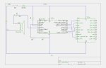
Anyhoo, if I use simple 3x 10k metal-film(1%) potential-dividers between the Picaxe output pins and the Xbee to correct the voltage levels, the modules transmit and receive data beautifully, but with the divider on pin-9 of the Xbee module(sleep mode pin), and the Xbee programmed for Pin Hibernate, so that the Xbee sleeps with a 3.3v high on it's pin 9, the module will not sleep for about 10 seconds, at which time it does sleep and everything is fine. During the 10-second waiting period, there is a 5v high on the Picaxe output pin, and 3.3v measured directly across the Xbee sleep pin and deck, so the Xbee SHOULD be sleeping...
After the 10 second initial waiting period, the module will wake whenever the Picaxe output pin goes low, and sleeps immediately once the message has been transmitted, and the Picaxe has pulled pin-9 of the Xbee high again.
This only ever happens on initial start-up, and confuses me.
I've written to Digi, but have yet to receive a response to this specific issue(perhaps they are trying it for themselves before they reply - Digi seem pretty good on replies to questions)
So, I am wondering if anyone else has had this issue when interfacing the Picaxe to the Xbee modules AND are using the Xbee's sleep mode.
See attached GIF of the schematic, which shows how I have things connected up.
As I say: This works beautifully to drop the 5v TTL from the Picaxe to CMOS 3.3v level for the Picaxe, and data transmissions and reception is just fine, it's just that the same divider won't work on the sleep pin of the Xbee, and I want to find out why.
I generally don't use any divider at all on Xbee pin 2(DOUT, Data-Out), as this tends to be connected directly to the Picaxe as it is less then 5v, or directly to a MAX202 arrangement for connection of the Xbee to a PC port.
IF I BREAK THE 3x 10k RESISTORS TO DECK ON PIN3 AND PIN9 OF THE XBEE, SO THAT PIN3 _AND_ PIN9 OF THE XBEE ARE ESSENTIALLY FLOATING, THE MODULE SLEEPS IMMEDIATELY ON POWER UP.
If I reconnect the 3x 10k resistors to deck on EITHER PIN3 OR PIN9 OF THE XBEE, THE MODULE REFUSES TO SLEEP.(during this test, I reconnected the potential-divider to deck on pin9 of the Xbee FIRST - the module stays awake, so then I disconnect it - the
module sleeps right away, so I then reconnect the potential-divider to deck on pin3 of the Xbee - the module stays awake.)
If I rig up a test as in the attached GIF, and put 5v on the top of the divider, so that there is 3.3v on the Xbee pin, the module sleeps immediately. If I measure the voltage on the Xbee pin upon power up when connected to the Picaxe, it is also 3.3v, but in this case, the Xbee won't sleep for 10 seconds.
Is this not a weird one?(rhetorical)
Any comments/suggestions/hints/large hammers?
Xbee's and Picaxe's are a perfect match for RF data-related projects, and I have used lots of Xbee's(series 1, pro @ 100mW). Their range and performance cannot be beat when compared to other more expensive RF-data modules.
However, I have run into a little problem with respect to sleeping the modules.
In all cases, PICAXE chips used are either the 14M or the 18X - primarily the 18X, as it allows me to program more message text into the code, with the higher memory of the 18X.
Anyhoo, if I use simple 3x 10k metal-film(1%) potential-dividers between the Picaxe output pins and the Xbee to correct the voltage levels, the modules transmit and receive data beautifully, but with the divider on pin-9 of the Xbee module(sleep mode pin), and the Xbee programmed for Pin Hibernate, so that the Xbee sleeps with a 3.3v high on it's pin 9, the module will not sleep for about 10 seconds, at which time it does sleep and everything is fine. During the 10-second waiting period, there is a 5v high on the Picaxe output pin, and 3.3v measured directly across the Xbee sleep pin and deck, so the Xbee SHOULD be sleeping...
After the 10 second initial waiting period, the module will wake whenever the Picaxe output pin goes low, and sleeps immediately once the message has been transmitted, and the Picaxe has pulled pin-9 of the Xbee high again.
This only ever happens on initial start-up, and confuses me.
I've written to Digi, but have yet to receive a response to this specific issue(perhaps they are trying it for themselves before they reply - Digi seem pretty good on replies to questions)
So, I am wondering if anyone else has had this issue when interfacing the Picaxe to the Xbee modules AND are using the Xbee's sleep mode.
See attached GIF of the schematic, which shows how I have things connected up.
As I say: This works beautifully to drop the 5v TTL from the Picaxe to CMOS 3.3v level for the Picaxe, and data transmissions and reception is just fine, it's just that the same divider won't work on the sleep pin of the Xbee, and I want to find out why.
I generally don't use any divider at all on Xbee pin 2(DOUT, Data-Out), as this tends to be connected directly to the Picaxe as it is less then 5v, or directly to a MAX202 arrangement for connection of the Xbee to a PC port.
IF I BREAK THE 3x 10k RESISTORS TO DECK ON PIN3 AND PIN9 OF THE XBEE, SO THAT PIN3 _AND_ PIN9 OF THE XBEE ARE ESSENTIALLY FLOATING, THE MODULE SLEEPS IMMEDIATELY ON POWER UP.
If I reconnect the 3x 10k resistors to deck on EITHER PIN3 OR PIN9 OF THE XBEE, THE MODULE REFUSES TO SLEEP.(during this test, I reconnected the potential-divider to deck on pin9 of the Xbee FIRST - the module stays awake, so then I disconnect it - the
module sleeps right away, so I then reconnect the potential-divider to deck on pin3 of the Xbee - the module stays awake.)
If I rig up a test as in the attached GIF, and put 5v on the top of the divider, so that there is 3.3v on the Xbee pin, the module sleeps immediately. If I measure the voltage on the Xbee pin upon power up when connected to the Picaxe, it is also 3.3v, but in this case, the Xbee won't sleep for 10 seconds.
Is this not a weird one?(rhetorical)
Any comments/suggestions/hints/large hammers?
Attachments
-
 3.3 KB Views: 49
Last edited: