Controlling camera shutter using I.R. remote

tt92

Member
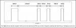
My Canon G2 camera has an I.R. remote sensor that responds to a bitstream similar to that sent by infraout. 38 KHz, bit-lengths and spacing the same.
The infraout protocol won't work, because I need to send a start bit and 32 data bits. Can I send timed bursts of PWM to an I.R. LED to simulate this? If so, how do I time them?
I understand that PWM in the background is used to control motors and so on, but I wonder
1. Can a 38KHx PWM at 50% duty cycle be somehow modulated to an output pin on the picaxe?
2. Can a 38KHz pulse be switched on and off quickly and reliably enough to simulate a pulse stream similar to the stream sent by infraout?

I use the Canon cameras in the bush, unattended, to photograph lyrebirds and bowerbirds. I take an exposure every ten seconds for two hours, and the timing mechanism I have made is about the size of half a brick and has a relay requiring 12 volts. If I can get the picaxe to do it, the whole thing would fit into a four- AAbattery case together with two batteries.

I have experimented with the 08M and can use pulsout to send unmodulated pulses of the right timing. I feel I am close, but I need help.
All responses will be valued.
 

BeanieBots

Moderator
I doubt you can turn PWMout on and off quick enough but if you OR it either with a gate or diode OR, then you can turn it on/off with any other output pin. This technique can be used with serout for sending serial comms. There might be scope with the method for your application.
 

LizzieB

Senior Member
My canon has a jack for a wired remote in addition to the IR. It's a lot easier to control it using the wired remote connection if you have that option.
 

bgrabowski

Senior Member
This is very interesting, I would like to know how you get on. Can you also let us know the details of the protocol and timings or give a website where they can be referenced. A 'bit-banging' method for Sony IR was developed by one of my A level students and details are available on Hippy's website.
 

tt92

Member
This is very interesting, I would like to know how you get on. Can you also let us know the details of the protocol and timings or give a website where they can be referenced. A 'bit-banging' method for Sony IR was developed by one of my A level students and details are available on Hippy's website.
I disconnected the I.R. LED from a cheap I.R. remote that successfully operated the shutter of the Canon G2 and G3 and replaced it with a connection to the mic input of a computer. (Through a voltage divider) I looked at the input using Audacity software, and got a good trace that showed me the timing when measured against the time scale on the display. It is very close to the timing generated by infraout as described in various picaxe publications. I was directed to a site for LIRC which listed some codes but I'd stay away from there. I followed a link or two and ended up infected with some dreadful virus. Counting the 32 bits on my Audacity display showed that I need Hex 538DF807. I think that 538D is a pre-data string, and is required for any Canon G2 command, and F807 is the shutter command.
 

tt92

Member
My canon has a jack for a wired remote in addition to the IR. It's a lot easier to control it using the wired remote connection if you have that option.
My Canons (G2 and G3) have only the I.R. remote.
They do have a USB connection but I don't understand it and I am hesitant to experiment with it. I can't fry anything with a mis-applied I.R. signal but if I did something dire with a USB connector, the camera could expire without even the courtesy of a puff of smoke.
 

Dippy

Moderator
Can't you feed your PWM into an external thing like a transistor or op-amp or logic and modulate that with a PICAXE pin? i.e. PWM running all the time at 38kHZ and you simply turn the tap on and off.
 

Dippy

Moderator
Oh arr!
Yes. You said it first and I missed it. Must be Alzheimers creeping in...
Sorry, my mind was distracted.(yeah, yeah!)
 

tt92

Member
Can't you feed your PWM into an external thing like a transistor or op-amp or logic and modulate that with a PICAXE pin? i.e. PWM running all the time at 38kHZ and you simply turn the tap on and off.
This is sort of what I had in mind, but it is a bit beyond me, I think. The 08M can have a PWM running "in the background" which I take to mean that I can start it running and then have the picaxe do something else. I was trying to work out if that something else could be to take the background PWM from an output pin into an input pin on the same picaxe and modulate it and output it to the I.R. LED. Are you suggesting I use one picaxe to generate the PWM and another to modulate it? Or are you saying that I can use the one 08M to output the PWM to itself, through a transistor?
I can't see how to "turn the tap on and off" with accurate timing, unless I can somehow direct that background PWM using pulsout. I am new to picaxe, as you can see. Thirty years ago, pre-P.C., I was doing this sort of thing on single-board computers, each worth about half a small car, burning EPROMs and writing 6502/6809 assembler.
I prefer picaxe.
 

eclectic

Moderator
tt92.
A few questions please.

1. Your "brick" controller. How does it work?

2.
Counting the 32 bits on my Audacity display showed that I need Hex 538DF807. I think that 538D is a pre-data string, and is required for any Canon G2 command, and F807 is the shutter command.
This gives a 32 bit code (see pic).
What are the millisecond timings?

3. I assume you've hacked the shutter button on a cheap R/C control?

e
 

Attachments

BeanieBots

Moderator
You can switch the PWM on/off using another pin on the same PICAXE.
(is my earlier post #2, totally invisible???)
You can either OR the two signals or AND them using a single gate. Then pulsout would "turn the tap on and off". ON for a high pulse if you use an AND gate. If you don't want to use a gate, then do it with diodes and maybe a tranny for a buffer.
 

tt92

Member
tt92.
A few questions please.

1. Your "brick" controller. How does it work?

2.


This gives a 32 bit code (see pic).
What are the millisecond timings?

3. I assume you've hacked the shutter button on a cheap R/C control?

e
The brick is a butchered "six-in-one" remote from Hong Kong (ebay) turned on and off by a "Flexitimer" built from a kit described in Silicon Chip. The relay in the Flexitimer runs at 12 volts, so the brick consists of the flexitimer, the butchered remote, and ten batteries.
Mark 2, finished today, is a really gutted remote timed with a picaxe activating a solid-state relay, all powered by two AA batteries. This all fits into a switched battery-holder designed to hold four AA batteries.
Mark 3, with any luck, will do away with the remote and consist of a picaxe, a transistor and two batteries.
The timings are
start 2.4
zero 0.6
one 1.2
inter-bit 0.6
 

tt92

Member
You can switch the PWM on/off using another pin on the same PICAXE.
(is my earlier post #2, totally invisible???)
You can either OR the two signals or AND them using a single gate. Then pulsout would "turn the tap on and off". ON for a high pulse if you use an AND gate. If you don't want to use a gate, then do it with diodes and maybe a tranny for a buffer.
Your post wasn't invisible but was over my head.
Anything more complicated than a transistor is beyond me.
A naked picaxe and a page or two of coding is what I can handle.
 

Tom2000

Senior Member
I was trying to work out if that something else could be to take the background PWM from an output pin into an input pin on the same picaxe and modulate it and output it to the I.R. LED.
I think he had something like the attached sketch in mind.

Good luck!

Tom
 

Attachments

Dippy

Moderator
Nice and neat. Sweet.

Does he need more oomph for this project though? I have seen no clues about expected ranges and ambient conditions.

Note: Everyone - please go and read Post #2 or else BB will explode like a PICAXE wired to the mains ;)
 

Michael 2727

Senior Member
Useful info about using Audacity, I'm just downloading it now for a try.
I bought a PENTAX remote "F" and a Konica shutter remote from the junk bin
at the camera shop $2 bucks each,, hey the batterys are worth more than that :)
 

eclectic

Moderator
This won't directly help tt92 , but some of the principles might.

I own an “old” Nikon D70 c/w an ML-L3 IR remote.
I found the Nikon R/C protocol here:
http://www.bigmike.it/ircontrol/

I used Acrylic's circuit. Cheap IR LED and 100 ohm resistor.
PWMout on pin 2. “Control” on pin 1
3 x NiMH AA.

Got the 'scope ready.
Tried a first draft of a program.
Code:
'** All timings are approximate and not tested

#picaxe 08m
setfreq m8
'** All timings are approximate and not tested
high 1 ;LED OFF
pwmout 2 , 52, 105  ; 38000 from wizard

for b0 = 1 to 5

pulsout 1,400 ; ON 2000uS
	pause 56 ;off 28 mS
pulsout 1,77 ;ON ~390 uS
	pause 3; off 3 mS	
pulsout 1,82 ; ON 410 uS
	pause 7 ; off 3.5 mS
pulsout 1,80 ;ON 400 uS
	pause 100 ;off 50 mS

next
It worked first time! Talk about gobsmacked!

e.

ps 1. Yes, I did read BB's post.
ps 2. The Nikon protocol looks simpler than the Canon,
but the pulsouts/pauses look achieveable.
 

Michael 2727

Senior Member
eclectic, what were you using to capture the data string in the shot you posted.
(prolly part of a $1,200 scope)
I thought it was a function in the Audacity program :(, it's still a neat audio tool
I'll keep playing with it. ( get the plugins as well )
 

eclectic

Moderator
Michael.

It was part of the Windows calculator display.

Captured using the Vista Snip tool.
(One of the very few Vista features I like)

It can also be done with screen-capture and Photoshop,
but it's a lot more hassle.

e.
 

Attachments

westaust55

Moderator
As an option have you considered using a PICAXE output to switch the signal using say SEROUT but modulating the LED to 40kHZ with a 555 timer.

See the attached diagram for a circuit to modulate at 40kHz

Have not thought about the total current load too much.
If less than 20mA, then you could conenct the +5V point to the PICAXE output.
But I would go for a transistor as a buffer to protect the PICAXE against over current.
 

Attachments

Last edited:

tt92

Member
Back to the soldering iron. I'll have a think about the current drain before I try either circuit.
I don't know if an I.R. LED straight from the picaxe has enough oomph. Time, and a bit of frustration, will tell.
A comment or two.
Audacity is an audio-editing tool and reacts in various ways to pulses, depending in large part on the sound card in the computer. It has a zoom icon which will expand a trace sufficiently to give a good measurement of pulse duration, but can do strange things with pulse direction. That is pretty much the limit of its usefulness in this application.
The Canon G2 and G3 both have a LCD screen. If you point the I.R. remote directly at the lens, the I.R. shows as white flashes. So you can tell that it is, at least, sending something.
The white flashes from the genuine remote appear bright. The white flashes from an I.R. LED direct from picaxe are not as bright.
 

Dippy

Moderator
Not as bright? Hardly surprising. But at least you can test/try at close range. It's an easy matter to beef up the output once you've got the comms working.
 

tt92

Member
I think he had something like the attached sketch in mind.

Good luck!

Tom
This has got me tossed.
Doesn't this mean the IR LED is on all the time?
Does this circuit mean for the pulsout to be switched on and off by the PWM?
I thought the PWM was to be switched on and off by the pulsout.
 

Texy

Senior Member
This has got me tossed.
Doesn't this mean the IR LED is on all the time?
Does this circuit mean for the pulsout to be switched on and off by the PWM?
I thought the PWM was to be switched on and off by the pulsout.
No its doesn't mean the LED is on all the time. The PWM signal IS ON all the time (by ON, I mean going ON and OFF at 38khz), but if the 'other' output pin from the 08M is high then the LED will not light - the 'other' pin needs to be low in order for current to flow through the LED. This 'other' pin is what you use to make the signal either 'ON' or 'OFF' (although it is still modulating at 38khz due to the PWM signal coming out of the picaxe).
Texy
 

Dippy

Moderator
Eh. The current flow through the LED is always on. V+ >>> RES >>> IR-LED >>> GND.
And always on until you start modulating the 38Khz at which point the transistor shorts the LED.

I couldn't understand why the LED isn't in series between R and Tr.?
(BUT I didn't like to ask just in case it made me look thicker)

Anyway, you're still limited to a limp 25mA. Needs a bit more. For a reasonable range esp if outdoors you'll need well over 10x that current. So an extra stage is needed really.
 
Last edited:

Michael 2727

Senior Member
Hmmm, I thought it was too good to be true.
I thought someone had finally found an App that you could point an IR
Remote at and get code displayed back, it'll happen one day.

Many IR LEDS will run continuous currents of 50mA and peaks of 100mA
for a short duration. Pulsed at 38kHz and a single burst you can sometimes
run at 2x or 3x that current. (Some LEDs will some won't) RTFM.

Run the (picaxe output) led off a 2N7000 MOSFET at 5V with a 47 Ohm
resistor will give you around 74mA drive, that should frighten the hell out
of most LEDS and probably won't hurt a good IR LED unless you hold the
button down too long.
You should get a few meters out of that. I would think the camera has
Good visible light filtering on it's IR detector even in daylight/outdoors.
 

Texy

Senior Member
Eh. The current flow through the LED is always on. V+ >>> RES >>> IR-LED >>> GND.
And always on until you start modulating the 38Khz at which point the transistor shorts the LED.

I couldn't understand why the LED isn't in series between R and Tr.?
(BUT I didn't like to ask just in case it made me look thicker)

Anyway, you're still limited to a limp 25mA. Needs a bit more. For a reasonable range esp if outdoors you'll need well over 10x that current. So an extra stage is needed really.
I wasn't refering to the transistor version of the circuit, but the version by acrylic.

Texy
 

Dippy

Moderator
Texy, you confused me which isn't too dificult I admit. Go back and check your reply #29. You replied to tt92's post #28 who referred to Tom's post/sketch.
- hence confusion.
No big deal, but I've hired out my Crystal Ball to Mystic Meg :)

Those cheap SFH484 485 IR LEDs can bang out oodles (over an amp pulsed). And some big-oodles (pulsed). Opto Diode do some fatties.
As you say so gently, read the Data Sheet and check the graphs.

I'd try and get it working before the ensuing argument about driving an LED starts...
 

jodicalhon

New Member
Well, I've had another go. :)

You can adjust the IR LED current by varying the 100 ohm resistor. You could probably up the base resistor value without problem. And you could change the BJT to a 2N7000 mosfet, as Michael2727 suggests, too.

The base resistor and the 1N4148 diode provide AND logic.

Edit: You could probably drop the 100 ohm altogether by using a larger resistor on the base of the transistor. I know from experience that 100k on the base of a BC548 will limit the collector current to around 20mA or thereabouts. I'm not sure what 47k might limit it to, but you could have a play.

Another unknown is how a large base resistor might affect the PWM waveform that comes through to the transistor. The large resistor and any internal transistor capacitance might create an unacceptable delay, and kill the PWM signal.
 

Attachments

Last edited:

eclectic

Moderator
Tt92.
Can you provide a little more information on the Canon timing?

The attached pic is from the url mentioned in my post #22

http://www.bigmike.it/ircontrol/
It show the timings for the Nikon R/C.

When I built my circuit, the 'scope trace looks like
the waveform in the picture.
And it works. with Acrylic's first circuit.

Your derived Canon protocol is something like

(2.4Hi) 0 1 0 1 00 111 000 11 0 111111 00000000 111

from your hex description.

538DF807

Could you provide times for each of the twelve blocks of Hi/Lo?
Or a diagram, similar to the picture?

ps I may have made a typo in the binary number.
 

Attachments

tt92

Member
When I work out how to do it, I will post the Audacity trace from the supplied IR remote, and the Audacity trace from my various attempts using the various circuits that have been suggested.
I seem to be reproducing pulses of appropriate spacing, but the camera doesn't respond. I must be close.
 
Last edited:

eclectic

Moderator
tt92

ALT PrtScr

then paste into Paint.

Save as a jpg (not bitmap.)

(first three should be in the helpfiles for windows.)

Attach to a post, using "Manage Attachments"

e
 
Last edited:

westaust55

Moderator
tt92

ALT PrtScr

then paste into Paint.

Save as a bitmap.

(first three should be in the helpfiles for windows.)

Attach to a post, using "Manage Attachments"

e
you will need to select and save in .jpg format from Paint.
The .bmp which Paint offers in the first instance cannot be uploaded on this forum.
 
Last edited:
Top