@Axel87, not replaced by, two separate issues I suspect.
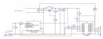
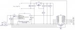
The diode D1 was not required and constituted a voltage drop of 0.7V across the diode.
The electrolytic capacitor C5 I suggest is a bulk/decoupler, removing noise and acting as a voltage reservoir to prevent the +ve rail sagging in any way when the IC is switching. Similarly C6 is a decoupler for the Picaxe chip. I suggest that this 'standard decoupling' was probably added, not to make the circuit work, but to add a few guarantees and increase immunity to unanticipated noise.
Note: two types of capacitor are commonly used for decoupling, small ceramic 100nF which deal with the high frequency noise and 10uF to 100uF electrolytic capacitors that deal with potential supply voltage excursions due to instantaneous heavy current demand. The method of construction of electrolytic capacitors makes them less than ideal low ESR (Effective Series Resistance) components and the smaller ceramic covers the gap. Between them they effectively remove all the noise that the MCU and driver chips generate internally.
Decoupling is the icing on the cake. it's still a cake without it, but isn't complete and may not work quite as well either.
I hope that has helped your understanding.
Earlier I noticed someone mentioned that he had been a radio amateur in his youth and decoupling wasn't quite the same issue as it appears to be today. This is very true, as in the interlude fast logic switching devices have become the norm and they produce a lot of noise internally. It is not uncommon to decouple every package with a 100nF ceramic capacitor and a bulk decoupler on prime candidates or looking after small groups of packages. Quite a step up from previous analogue usage I suspect.
Zeroeth Commandment (programmers start at 0 and not 1) Thou shall consistently decouple, heavily!
")
 95.8 KB Views: 314