Picaxe clock

Tec_

New Member
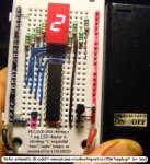
well im fairly new to the picaxe i have a electronics background but i don't know S**T about programing. iv been working on a picaxe controlled LCD project that is like 94% done. and ive stumbled my way through most of it.

i was looking at doing a 7 segment display clock and i was wondering if any one could point me towards a tutorial or a project log using a picaxe 18x

thanks guys and if you want i could post what i have with my LCD project
 

marcos.placona

Senior Member
Ok, first things first. What exactly do you wanna know about the picaxe 18x? Is that it's integration with the seven segment displays? If it is, I can only recommend that you take a look at the interfacing manual (manual 3), where it shows 1-2 ways of doing this integration.

In regard to the clock, you'd probably need to use another IC for that, as the picaxe itself is not really reliable for counting time.

I'd go for anyone from Dallas family or to the simple PCF8583 (people over here will probably suggest something different. There's many choices)

But for now, could you give a bit more details about your project? I mena, If you have the LCD, why would you go back to the 7 segment displays? They can be sucha pain to wire up, and waste a lot of memory on the programmming side.
 

Tec_

New Member
well what i would like to do is to build a 7 segment display clock. i like the way they look and i don't want to buy a new LCD (the one i have will be in use)

i was going to do it with a 555 but my professor said that his was greatly affected by temperature and that a PIC would be the way to go. so i figured, i have some picaxe 18x's why don't i use those. ive seen this project done before with different pic's i just would like to use what i have.
 

MBrej

Member
The easiest way to control a few 7 segment digits is to use a dedicated IC such as MAX7219, which will control 8 digits from 3 PICAXE pins. There are other similar ones available from maxim, just look through the LED display section. Remember you can free sample them ;)

As for keeping the time you will need to use an external IC which has a watch crystal to keep the time. Another tried and tested one here is the DS1307. Again there are others available with different interfaces, and some with built in crystals (if you don't mind soldering surface mount)

You will most likely need a 18X, as you will need the inputs/outputs, and it has I2C support needed for that clock.

Matt
 

hippy

Technical Support
Staff member
Ask your Professor what he thinks about using mains cross-over signalling as an accurate timing source.

One important design criteria is whether your clock needs to keep accurate time when power is lost or if you're happy to have it show flashing "00:00" or similar after a power fail.

As you've seen other PICmicro projects doing the same as you want, they should be a valuable resource for different ways to connect 7-segment displays to a micro. To replace with a PICAXE you simply need to ensure the control signals go to PICAXE output pins and write the software. What the software will be depends on what hardware you choose.
 

Tec_

New Member
it doesn't mater to me if it has to be reset after loosing power

as for using mains he said its been done for some time using synchronous motors that are done mechanically. the motor will rotate once a hour and the rest of the hands are moved mechanically. or you step the line voltage down to 3 or 5 volts and run it through a comparator and clamp it to get a nice square wave that you can then use to count.
 

MPep

Senior Member
Hi Tec,

And welcome to Picaxe world.:)
The mains synchronisation is to do with the fact that you can count how many times the signal crosses through 0V, remember it is a Sine wave.
Now depending on where you are, you need to count to 50 or 60 to know that 1 minute has passed. If the mains are at 60Hz then you can easily count seconds as well!

Mark.
 

manuka

Senior Member
-its been done for some time using synchronous motors that are done mechanically. the motor will rotate once a hour and the rest of the hands are moved mechanically-
Gasp-clocks with motors & HANDS. This is 2008 - not 1908!

In an era of $2 watches offering split second features, is it REALLY worth making a 7 seg clock??? If not mains powered it'll be a battery hog of course too. Sure - 7 segs are fun, but - ahem- a clock ???

How about considering the new & cheap 20M which of course has enough outputs to light all 7 segs + DP "as is" & use it to put up really useful "messages" such as temperatures, caller ID, phases of the moon, high tides, bus arrivals -or days until classes end!? LED matrix arrays (especially 5x7 shown below) have considerable scope too. Stan
 

Attachments

Last edited:

Tec_

New Member
i could do something crazy but like i said i dont know much about the programming portion of this. that’s why i just want to build a clock. though a count down timer would be cool as well
 

manuka

Senior Member
Tec- excuse these boring Q's, but they'll help us to better appreciate your quest. This esteemed forum receives many educational calls for help (including some just hours before a submission deadline...) & the classic things we REALLY need to know include -

Your age? Where are you? Experience? Resources? Facilities? Budget? Time frame? What academic course ? How assessed? Help allowed? Project presentation needs - PCB? Documentation needed? Mmm- perhaps even your profs. background!

After an LCD workout you'll find LED segments pretty easy to drive, so don't worry too much about the programming! That 20M circuit shown above has code => http://www.picaxe.orconhosting.net.nz/20m7segds.bas & schematic => http://picaxe.orconhosting.net.nz/20m7segds.gif

THOUGHT: How about a 101:101:101 style binary clock - this would be a real teaser!
 
Last edited:

Tec_

New Member
Tec- excuse these boring Q's, but they'll help us to better appreciate your quest. This esteemed forum receives many educational calls for help (including some just hours before a submission deadline...) & the classic things we REALLY need to know include -

Your age? Where are you? Experience? Resources? Facilities? Budget? Time frame? What academic course ? How assessed? Help allowed? Project presentation needs - PCB? Documentation needed? Mmm- perhaps even your profs. background!

After an LCD workout you'll find LED segments pretty easy to drive, so don't worry too much about the programming! That 20M circuit shown above has code => http://www.picaxe.orconhosting.net.nz/20m7segds.bas & schematic => http://picaxe.orconhosting.net.nz/20m7segds.gif

THOUGHT: How about a 101:101:101 style binary clock - this would be a real teaser!
well im 20. and i will be graduating on the 5th with a degree in Electronics Technology. so im loosing all of my access to the lab's there is a chance that i will still be able to keep in touch with my professors through the internets. but i do have my own work room in my basement with power supplies, o scopes and other various tools.

tho the binary clock would be cool, i don't want to think when i look at it:D
 

marcos.placona

Senior Member
"tho the binary clock would be cool, i don't want to think when i look at it"

Remember when you were 7 and every time you had to look at your kitchen wall clock you had to count to know the exact time? i.e. small needle @ 7 and bigger needle @ 6. You also had to learn it, so you could interpret that it was actually 7:30.

Binary goes to the same way, it's just interpretation.

Here's an example of a binary clock I've made some time ago. Just visual though, but very easy to read.

UPD: Here's a real one that uses the same idea I've used on mine.

http://www.gadgets.co.uk/item/BINARYW/Binary-LED-Watch.html
 

Dippy

Moderator
Back to the plot...

Tec, may I ask a question that may sound cheeky but isn't meant to.

It's just that you didn't comment on MBrej's link to that very useful MAX LED driver chip which would have done all the hard work for you. Combined with his other suggested link of the DS1307 (which has Bat backup facility for time not the LED display) I would have thought that was all the hardware you needed - along with an 18X.

So, can I assume that you just want circuit and code details you can make and copy? (Almost a kit). Can I also assume this isn't a college exam-mark-related project?

I think when I look at analogue clocks I look at the position of the minute hand, not at the number to which it pointed. As in the big hand is halfway round, so it's half-past. Most people do.

Obviously make this on breadboard or suffer the Wrath of Stan - and lo(o)se his respect.
 

Tec_

New Member
well ware to start

@ marcos.placona
no, i get Binary. i had a hell of a time in the beginning of boolean algebra. but i would like it to be normal 7 segment.


@ Dippy
i didn't mean to glaze over MBrej's link i may yet try those chips. (i showed them to my professor and he thinks he may have a new project for the new students) and as of right now i have no idea what im looking for. kit or not, i don't think i want to develop this thing on my own. i would like to have some one's work to go back and compare mine to.

@ the rest
keep the ideas coming (and links) the more stuff i can look at the more i can wrap my head around what i want to do.

and no this is not for school its for fun on my own.
 
Picaxe 18

I have successfully used the 28X series with a Dallas 1307 RTC to operate both 7 seg and nixie clocks. More pins more options. You could use the 18X with some registers or latches such as the SN74LS374.
 

Thomas Henry

New Member
Back in 1989 I did a fairly extensive alarm clock design with the Motorola 68705 microprocessor which used the power line (mains) frequency as a timebase. It, too, used a multiplexed LED display, with the MPU doing the multiplexing. The result appeared in my article "68705 Microcontroller," Radio-Electronics, October 1989, p.83, 86-89. Many university libraries (at least in the US) have archived this on their shelves if you'd like to see how I conditioned the power line signal.

Anyway, while voltages swing all over the place in this country, the AC frequency is usually quite accurate in the long term. I found the clock worked very well, and in fact had it on my desk at the University for many years (I was a professor of Computer Science back then).

Thanks for the memory jog---I think I'll try this with the Picaxe now!

Thomas Henry
 

westaust55

Moderator
i could do something crazy but like i said i don't know much about the programming portion of this. that’s why i just want to build a clock. though a count down timer would be cool as well
You want a clock, then try this version:
http://www.youtube.com/watch?v=vCgMDY-Sg1Q

:)


Seriously though, if a clock is what you want to build for some initial hands on electronics experience then so be it.

You may be better off to just get a few LED's flashing first (if not already done) to get some programming and a simple working project under your belt.
A project working can build up your confidence to work on more advanced projects.
 
Last edited:

Thomas Henry

New Member
Hola Tom,

If you'd like to try a line-derived timebase, I have a sketch and some Picaxe code here.
Thanks for the resource. In your page, the first software listing comes through fine, but not the second. (It generates a page not found error). This is the software for a line frequency based timebase, which I'd be curious to see how you accomplished.

Anyway, neat project!

Thomas Henry
 
Top