I just bought a few of these mailorder from usa and now am finding it hard to get something to fit the 3 pin connector. Just wondering if anyone has a d.i.y. way of making a connector or where I could "recycle" one from? Even if it was 3 single push on type connectors? Is there such things? I don't mind making something and heatshrinking it into something that's reliable and sound.
Sharp gp2d12 i.r.sensor connectors
- Thread starter nzdragme
- Start date
It would help to show the thing! Is this it => www.lib.sfu.ca/about/surrey/equipment/sharpgp2d12.jpg ? What is pin spacing? A quick glance reminds of an ex. PC CD -> sound card connector. Checked a Jaycar catalog? I've made all manner of DIY plugs & sockets over the years, with some (cell phone charger sockets etc) incredibly fiddly- hot melt glue,heat shrink & a soldering "helping hand" are your friends. Stan
")
I just bought some of these http://cgi.ebay.com/single-row-square-50x-male-and-25x-female-pin-headers_W0QQitemZ230254689024QQihZ013QQcategoryZ109438QQcmdZViewItemQQ_trksidZp1713.m153.l1262
More header pins and sockets than I will ever use. Cut off what you need, eg 3 pins then solder and hot melt glue as manuka suggests.
More header pins and sockets than I will ever use. Cut off what you need, eg 3 pins then solder and hot melt glue as manuka suggests.
Last edited:
Mycroft2152
Senior Member
The Sharp Sensorsr does NOT use the standard 0.1" connector.
They say a picture is worth a thousand words
Myc
Note: the sensor is also availible in an I2c version with standartd 0.1" connectors
They say a picture is worth a thousand words
Myc
Note: the sensor is also availible in an I2c version with standartd 0.1" connectors
Attachments
-
 57.9 KB Views: 24
Last edited:
marcos.placona
Senior Member
Bought some of those too, they come in sets of 36 pins connectors, and I can even suggest where to get them from in case you're in UK.I just bought some of these http://cgi.ebay.com/single-row-square-50x-male-and-25x-female-pin-headers_W0QQitemZ230254689024QQihZ013QQcategoryZ109438QQcmdZViewItemQQ_trksidZp1713.m153.l1262
More header pins and sockets than I will ever use. Cut off what you need, eg 3 pins then solder and hot melt glue as manuka suggests.
How much did the sensors cost? And where did you get them from?
Cheers
hippy
Ex-Staff (retired)
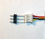
If I've followed correctly, the game at present is to find a socket which matches that on the right of your image.They say a picture is worth a thousand words
I'd be tempted to approach it from the other direction; get the pins to fit the socket ... bend the pins outwards until they fit a standard 0.1" socket ( and cut off any extra length of pins longer than others ), bend the pins and solder to a 0.1" molex, or simply solder wires to the board.
Mycroft2152
Senior Member
Hippy,
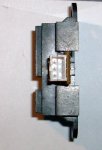
Sounds great in theory, but if you actually had one in your hands, you would see this is a mini connector with very short pins and a shield lock. You might be able to unsolder the connector (with great care) and resolder wires onto it.
The connectors are usually included with the senosr, or else are availible separately from the vendor.
Attachments
-
 110.9 KB Views: 11
 -
 115.6 KB Views: 12
Mycroft2152
Senior Member
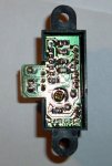
And here is the bottom:
Attachments
-
 148.2 KB Views: 13
NZdragme.
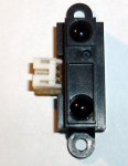
If it's this one (second one down),
http://www.active-robots.com/products/sensors/sensors-sharp.shtml
then it says
Supplied with 300mm connection lead (26 gauge stranded wire) one end of which has a machine crimped JST connector and the other end of the lead is left free.
So, you could either find JST connectors (and spend days waiting for delivery),
or simply wire your own version, as indicated by Stan, Dr-A and Hippy.
E
Mycroft2152
Senior Member
If your soldering skills are up to it, you could kludge a connector per S, H. and Dr-A.
BUT the risk is frying the sensor.
BUT the risk is frying the sensor.
Looking at the Sharp Data sheet shows it uses a "S3B-PH" connector.
http://www.farnell.com/datasheets/62635.pdf
Looking at the S3B-PH connector data sheet shows 0.5mm sq pins on a 2.0mm pitch.
http://www.jst-mfg.com/product/pdf/ePH.pdf
This is the same as standard 2mm pitch pin headers e.g. Harwin.
http://www.harwin.com/include/downloads/drawings/M22-713.PDF
No doubt numerous other makes of 2mm pitch pin headers/sockets are the same. Check them out for yourself.
If you can't find a S3B-PH connector and you don't want to bodge/bend or kludge, then you can use a header socket to solder some wires to. Little dollop of heatshrink and Job Done.