Picaxe-based Satellite: PongSat-18X

womai

Senior Member
One more idea regarding additional measurements - maybe a barometric pressure sensor, which could also give an idea about the height above ground? There may be several options for such a sensor; one is a vibrating sensor - the vibration frequency and/or damping changes with the density of air.

Wolfgang
 

amberiya

New Member
What unit is the period of a satellite orbiting Earth measured in and how can you prove this? For the equation, 2pi times the square root of an orbit cubed, divided by the product of the universal gravitational constant and the mass of Earth= period of a satellite orbiting Earth....What is the unit measured in? and prove this please?
 

womai

Senior Member
What unit is the period of a satellite orbiting Earth measured in and how can you prove this? For the equation, 2pi times the square root of an orbit cubed, divided by the product of the universal gravitational constant and the mass of Earth= period of a satellite orbiting Earth....What is the unit measured in? and prove this please?
Well, I'm not going to solve your homework for you, but here's the idea:

Assuming a circular orbit (i.e. not elliptical), and neglecting friction in the atmosphere, there are only two forces acting on the satellite:

- centrifugal force - wants to push the satellite away from earth and depends on the satellite's mass, its speed as well as the distance from earth

- gravitation - wants to pull the satellite towards earth and depends on the mass of the satellite, the earth's mass, and their center-to-center distance.

In order of the height to remain constant (i.e. circular orbit), those two forces must be equal (with opposite sign). Now all you have to do is look up the formulas for those two forces and do a tiny bit of math to get the satellite's speed. The it's trivial to calculate how long it takes to gp around a full circle.

Wolfgang
 

kranenborg

Senior Member
PongSat-18M2, PongSat-14M2 satellite options

I think that the 18M2 but in particular the upcoming PICAXE-14M2 (announced for 2011) would be ideal for making even more powerful and compact PongSats, even when using DIP packages (although a SMD 20X2 allows more on the same area, of course).

Looking at the circuit of the PongSat-18X a similar implementation with the 14M2 would lead to a drastic reduction in size since:

  • The 14M2 package will be smaller
  • the MAX6018 Voltage Reference IC can be removed because of the 14M2 internal Vref.
  • External pullup resistors no longer necessary, internal programmable pullups can be used instead
  • The clock IC (DS1337) can be dispensed with, clever use of the new Time variable will be a proper alternative
  • The C's in parallel with the LEDs can be dispensed with since a lot more direct ADC pins are available

However, one would like to do more than just replicate a circuit with a new device. In that respect I think that the comparator functionality (although not directly supported by a BASIC command but undoubtly possible to simulate by poking the proper control registers) can be very useful. From the PIC16F1827 datasheet I get it that the comparator can have as one of its inputs the output of the DAC. This would mean that there is the option to have a programmable input level to digitize incoming analog signals and filter out noise at run-time.

I myself am now thinking of starting a project on a successor to the Pongsat-18X which would include a PIN-diode based radiation detector based on the following appnote from Maxim: http://www.google.se/url?sa=t&source=web&cd=1&ved=0CBgQFjAA&url=http://www.maxim-ic.com/app-notes/index.mvp/id/2236&ei=W0lwTIipKISFOLjXyLAL&usg=AFQjCNEuNdxMebyuHJJ36GmWKVxDgVAmRw. The final comparator stage in the circuit diagram could actually be the PICAXE comparator and thus allow a programmable noise canceler.

Any other project ideas, suggestions? A forum project, perhaps?

/Jurjen
 
Last edited:

Vroom

Member
Great, just a question about 24LC512, 7pin WP what use connected to pos, neg, or just rest open?
 
Last edited:

MFB

Senior Member
This certainly sounds like an interesting project, with the low noise signal circuitry being especially challenging. My only concern is the count rate forms such a small detection area. Do you have an estimated count rate? Many years ago, whilst at Bristol University, I was involved in the design of instrumentation for a large balloon-borne cosmic ray detector that was flown from Palestine Texas. It used a gas scintillater that was about four metres in diameter and used 25 photomultipliers!
 

kranenborg

Senior Member
The challenges are indeed significant:

- Noise generation: The Maxim low-noise amplification circuit as presented in my last post should be adequate regarding just the amplification part (have just ordered the parts today and will start testing soon) but I think that the real challenge is the noise generation at the input, since a voltage of 12V for the PIN-diode needs to be generated using a PWM signal and voltage quadruple circuit, and there the PWM circuit could be a real noise generator in practice, with the noise generated on-chip in the PWM module (maybe use a PWM frequence as low as possible). Testing will show to which extent this is a real problem.

- Strong depence of PIN diode sensitivity on temperature

- Strong depence of battery voltage on temperature, and consequently also difficulties to generate a 12V diode voltage over a large temperature range, maybe the FVR can be used here (assuming that it is reasonably temperature stable over a large range, needs to be tested as well)

- Like MFB remarked, the small size of the PIN-diode detector area

There is however one single reason why I think this project may be successful in showing that radiation levels will increase with height, and that is that the temperature decreases monotonically below the tropopause and then increases again above it (as is very clear form the NLSE-1 results), allowing results to be compared with the same temperature levels at two different heights. I am thinking of implementing the maxim app note circuit using an 18M2 and using its internal comparators (see my note on using 18M2 comparators in the snippets section of the forum). If this all works after testing at ground level then this will become the NLSE-2 PongSat.

Regards,
Jurjen
http://www.kranenborg.org/electronics
 
Last edited:

kranenborg

Senior Member
Another PongSat application that may be interesting is to investigate whether electrical charge differences occur while traveling the atmosphere. We all know about charge differences in thunderclouds (I guess that it will be difficult to persuade JPAerospace to do a launch directly into such a storm ...) but it seems probable to be that even in clear skies considerable differences in electrical charge levels might occur. I could not find much relevant literature about it, so this somehow seems like an interesting research subject. I came to the idea when considering the new touch sensor features of the PICAXE-18M2 indicating capacity/charge changes: when wrapping the PongSat in aluminum foil both inside and outside the pongsat surface (i.e. creating a capacitor, the inside foil connected to GND of the electrical circuit) and taking a reference value at ground level and recording charge changes for each interval using the touch16 command, one should maybe get an impression? Is this something to pursue or is it total nonsense?

/Jurjen
http://www.kranenborg.org/electronics
 
Last edited:

eatabean

New Member
LED response frequencies

First post on this forum... I am totally new to the Picaxe, but hope to make a contribution here anyway!

I use a device called the Sun and Sky Station, made in the US by Radio Shack, to measure sunlight directly and indirectly, in 4 different wavelengths. The developer, demigod Forrest Mims III came up with a cheap and effective device that is also very stable over long periods of time.

I have not read anywhere on this thread anything about the wavelengths your diodes are most sensitive to. Have you taken this into consideration? Perhaps even more experiments could be performed by simply duplicating the device in different wavelengths. I have also read where the diodes give slightly different outputs, and should be matched and tested.

Another question: do you check your recorded data against a known reference? There should be some sort of zero to calibrate against. Perhaps I have missed this info. I am very impressed with the project and your ability, as shown here. In fact the entire group should be commended!

Perhaps most interesting... I live in Västerås ( about an hour's drive from Uppsala!)
Jim
 

a.a.mcmahon

New Member
Fantastic use of your time! I'm sure your inspiring a lot of others to do similar projects... as for the extreme low temperatures... a simple handwarmer placed in the device? Just a tiny tiny one near the battery would do, as the extreme cold hits the device that tiny, yet high, thermal energy will be very quickly conducted to the coldest parts of the device. There are some equations (Look at specific heat capacity equations) that can help you determine the theoretical amount you would need. It wouldn't be hard at all to make sure the device is warm but not so much so as to cause damage. Some sort of chemical reaction would be best for this very short experiment. Let me know if you need any more help!
 

kranenborg

Senior Member
New Pongsats planned: NLSE-2, 3 and 4 for 22 September Launch

Hello,

It has been a few years since our NLSE-1 (Pongsat-18X) near-Space Satellite was launched by JP Aerospace (www.jpaerospace.com) and sucessfully operated, as reported in this thread.

In order to have a cool summer project activity we have enrolled in the upcoming flight, planned for 22 September, now with three Picaxe-based satellites (and two of my sons taking part in their design):

- NLSE-2: Gamma ray detection using a reverse-charged PIN-diode as detector (see also posts #51 and 52 in this thread for background info). Furthermore we want to study the picaxe's behaviour at very low temperatures (internal RC clock drift as compared to watch crystal oscillator, we are open to discussion of more interesting experiments for testing semiconductor behaviour at low temperatures)
- NLSE-3: "Atmospheric sensing" Pongsat with temperature, pressure, tilt/vibration (= wind speed measure)
- NLSE-4: An alternative - fun but somewhat crazy - way of measuring pressure decrease with height using a marshmallow-based home-brew pressure sensor! (since marshmallow is the most popular material flown in pongsats). We have an idea on how to do it, using a lemonade straw, marshallow filler in it, a miniature potentiometer and some stiff wire ... .

The one that is technically most challenging is of course the NLSE-2 (but in a sense also NLSE-4). For the gamma radiation circuit we plan to use a variant of the one presented in the Maxim Application Note AN2236, and our circuit then looks as follows:

NLSE-2.JPG

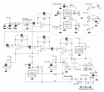
The circuit front-end part with the PIN-diode detector and subsequent amplifiers IC1a-b and IC2a is identical with Maxim's AN. However, I altered the end stage containing the IC2b stage and IC3 comparator: we use a programmable noise canceler circuit using the Picaxe-14M2 internal comparator, DAC and SR-Latch as discussed elsewhere recently on this forum (will post the final version of the noise canceler in the code snippets section soon). Since the PIN-diode sensitivity is very temperature dependant we include a DS18B20 temperature sensor, and all data needs to be stored in an EEPROM as well. There are a number of questions we have and which we would like to discuss here, all related to the power delivery for this satellite:

1. The circuit above shows two variants: either a 3.6V special Lithium battery (same as NLSE-1 which worked very well) or a solar cell based solution. Since the PIN-diode needs a higher voltage (>=12V) and a sensitive 4-stage amplification circuit is used, I am a lttle afraid that the step-up coverter circuit as shown in the right-upper part of the circuit will generate too much switching noise. Would it still be possible to make it work? (we will start buiding a prototype soon and check it with Womai's oscilloscope) If so we still may get everything into a pongsat if Womai's offer of providing an industry-grade PCB still stands.

2. We may however also opt for a MiniCube version (a new offering by JP Aerospace, see their website), a 5x5x5 cm box which provides for space to fit solar cells on its surface. I guess that this then would allow a very smooth power provision (also shown in the circuit). I expect that due to the high efficiency of solar cells at low temperatures there would not be a need for any MPPT-like circuit for boosting their efficiency. With an effective area per side of 20 cm2 and five areas I would presume that such a setup would provide for enough power. Any opinions here?

Any suggestions, critical remarks etc. are most welcome

Enrollment in JPA's upcoming launch by sending John Powell a mail and one's own PongSat or MiniCube is still possible for other forum contributors as well ...

Best regards,
Jurjen
 
Last edited:

kranenborg

Senior Member
prototype ready

Hello,

We have come so far as to have a working prototype version of the 14M2-based NLSE-2 (radiation detection). We're quite close to the deadline now (has been put forward one week). It will not be seated in a pingpong ball but in a MiniCube instead (which we got for free from JPA due to our NLSE-1 in 2008 being such good propaganda for them, it pops up at several places on their website ...). The included picture shows the prototype circuit, the photodiode and the Minicube (5x5x5 cm), the latter two covered with several layers of black paint in order to avoid light on the photodiode.

The prototype is functioning currently (with Womai's 2-channel DPSCope as an indispensable tool!), but does not have a RF-protective shell around it yet (which is definitely needed because of its extraordinary sensitivity). My goal is to tightly wrap the assembled minicube in aluminum foil all around. The foil helps in blocking most of the light as well.
I have two questions regarding this RF-shielding approach:
1. would one aluminum foil layer be sufficient?
2. Does it need to be connected to GND of the circuit (not so easy actually, but not impossible)

Best regards,
Jurjen
http://www.kranenborg.org/electronics
 

Attachments

Last edited:
Top