RGB LED Control using RS232 (Serial)

Robt0

New Member
Hi there!
This is my first post, and yes I have searched the whole forum on 'RGB LED', 'PWM LED' ... etc. There was nothing found, hence this posting :)

Down to business :-
I have searched t'internet and discovered that there are a few PIC based projects that can control RGB LED's (Red Green Blue Light Emmiting Diodes) using RS232 serial data. They are based upon the microcontrollers that the PICAXE is using. Using PWM (Pulse Width Modulation) through MOSFETs (Metal Oxide Silicon Field Effect Transistors) to alter the brightness of each of the three LED's, or each die in a common cathode or anode package.
Looking at the documentation and specifications for the entire PICAXE range it seems as though there are only a maximum of 2 outputs that can be 'background' PWM outputs.
I know that one can control stepper motors (servos) with up to 8 outputs but the ratio is only variable between 1:2000 to 1:8. This is not enough to drive LED's between off and an acceptable level of brightness.
What I wish to do is control an RGB LED (or three individual LED's) from a serial data line (RS232) to generate 'any colour' (well actually 8 bits per R,G, or B).
As one does not have access to the lowest level of the PIC, then trying to write my own accurately timed PWM loop may be impossible.
I may be missing something - I hope I am - but it seems as though the entire PICAXE range is unable to do this!
It would be great to utilise existing the PCB's (Printed Circuit Boards) and the obvious support that PICAXE provides with such a well designed system.
It is well within my expertise to program and construct the project, but there is no point in re-inventing the wheel, especially if there is a way to control 3 PWM outputs. I don't enjoy etching PCB's but I do enjoy getting something working quickly ;-)
I would appreciate this forums' thoughts on this matter.
Regards
Rob.

Note:-
The 'UK' based site that achieves what I wish to do is here -
http://picprojects.org.uk/projects/simplergb
The 'US' based site -
http://www.rgbled.org/
 

moxhamj

New Member
I'd do this three 08Ms, one for each led. Each can receive RS232 data and the data is very simple - message to (say) picaxe 2, turn led to xx value. Three 08M chips is still <$15.
 

Robt0

New Member
RGB control from RS232

I'd do this three 08Ms, one for each led. Each can receive RS232 data and the data is very simple - message to (say) picaxe 2, turn led to xx value. Three 08M chips is still <$15.
Thanks for the above. I suppose that I should have mentioned that I wish to control a 20x20 matrix (400 'RGB' LED's, or 1200 separate R G and B LED's).

The upshot of this means that using single 08M's I would need 1200 chips and associated PCB's (Printed Circuit Boards). The cost of this part of the system per RGB LED is thus multipled by 3 ... Instead of the 'control' part of the system costing (approx) GB£880 it will be GB£2,640. Not to mention the fact that I have to configure each 08M chip to accept a particular serial code. It was going to be enough of a problem controlling 400 individual RGB LED's - that would have fitted into a two byte address, followed by three bytes for the RGB values. Now the code will still have to be a two byte address, followed by a one byte value. Alternatively I could program each 08 to listen to the full message and only act upon the R G or B part ... but dealing with 1200 individually programmed chips is still harder than dealing with 400! :eek:

It looks as though, for this project, I'm going to have to design and build my own PCB's and write special RS232 and PWM code. I can do this, but it is work that I'd hoped I'd been able to find had been done before, thus saving me time and effort. :D

If I'm going to have to use different chips I'll probably go down the route of using PIC's with multiples of '3' outputs and associated 'hand crafted' PWM code to drive, say, 4 RGB LED's from a PIC that has enough I/O lines (eg PIC16F84, which has 13 I/O pins). I will "only" need 100 of these to control the matrix.

Even though the project will end up using PIC chips not sourced from the PICAXE stable - I'll keep this forum informed as to the project progress ...
assuming that anyone is interested, that is ;)

Thanks for your input "Dr_Acula".
Regards
Rob.
 

moxhamj

New Member
If you are building a big array then other solutions might be worth looking at. If you have a triangle or sawtooth wave generator that goes from 0-5V (2 op amp circuit) and then compare that with a voltage (one op amp) then it will produce a pwm signal. The comparison voltage can be sitting in a sample and hold and that can be just one capacitor. 4051 multiplexors can turn 1 analog input to 8 analog outputs and with multiple 4051s you can drive any number of sample and holds. So there is one triangle wave generator for the whole system and for each led you have 1/4 of an op amp (cost 7.5c) plus one capacitor (cost 10c) and 1/8th of a 4051 (cost 12c).

This sort of display would be very stable as it would have no flicker, but it would take time to update each sample and hold, so it would be good for static images but not so good for moving images.

If you are displaying moving images then the speeds get very high and the only solutions are probably going to be to get into machine code.

I wouldn't be getting any boards made until this is working on a prototype!
 

Robt0

New Member
Thanks for that idea. Interesting as the display will not be being updated vey quicky - allow 2 to 4 seconds for a complete 'image' change. Still want to specify the values using a serial protocol, but then all i need to do is map the 400*3 RGB values to individual comparators ... the R2R ladder seems to spring to mind here. Thanks for being a useful and helpful sounding board. I only hope that I can help you someday ;-)
Have fun
Regards
Rob.
 

moxhamj

New Member
A picaxe would be useful to take the serial data and turn it into an analog value via PWM. Then if you need to address 400 sample and holds, need 2^9=512 so 9 bits. One of the bigger picaxes like an 18X or 28X could do this. 4051s have some extra high and low enable pins that can be used as part of an addressing system so you might only need one 3-8 decoder or 4-16 decoder. Or even a long series of 595s in a row. This could be done with one picaxe and lots of 324 and 4051s.
 

gbrusseau

Senior Member
The TLC5940 is a 16-channel, constant-current sink LED driver. Each channel has an individually adjusted 4096-step grayscale PWM brightness control and a 64-step, constant-current sink for dot correction. All controlled via a serial interface.
 
Last edited:

papaof2

Senior Member
Just for future reference, the forum doesn't search for terms of 3 letters or less (RGB, LED, etc) but will accept RGB* or LED* and any other terms to go with them.

John
 

gbrusseau

Senior Member
With three TLC5940 chips at about three bucks a piece, you can control 16 RGB* LEDs.
These ICs are designed to be cascaded, so only one serial comm link is required to control all three of the chips.
 

gbrusseau

Senior Member
With 400 RGB* LEDs, that would be 75 TLC5940 ICs. All 75 ICs would still require only a single serial comm link. The TLC5940 drives common cathode RGBs directly up to 125ma. No external drivers needed. An external resistor determines the max constant current to all the LEDs. I have used these and can say they are easy to interface to a PICAXE. The comm link can run up to 3 mhz. You may want to consider an MPU other than the PICAXE that will communicate at 3 mhz. Maybe a CRAY.
 

Rookie

Member
To gbrusseau

With 400 RGB* LEDs, that would be 75 TLC5940 ICs. All 75 ICs would still require only a single serial comm link. The TLC5940 drives common cathode RGBs directly up to 125ma. No external drivers needed. An external resistor determines the max constant current to all the LEDs. I have used these and can say they are easy to interface to a PICAXE. The comm link can run up to 3 mhz. You may want to consider an MPU other than the PICAXE that will communicate at 3 mhz. Maybe a CRAY.
It's interesting... can you explain and post some graphics or diagrams of what you do?
 

gbrusseau

Senior Member
I use an 8M in 8mhz mode with pwmout at minimum pulse width and duty cycle (pwmout 2,1,1) for the TLC5940 grayscale clock generator, free running. Every 7 milliseconds the 8M pulses the TLC5940 BLANK signal pin high/low to reset the TLC5940 grayscale counter. Turns out that 7ms is almost perfectly 4096 pulses, which is what the grayscale clock pulse count should be before BLANK resets the TLC5940 grayscale counter. Doesn't need to be exactly 4096 pulses.

I'm using a much faster MPU (no mention of brand name) to independantly load serial data into the TLC5940 serial comm link. With 4096 grayscale-brightness steps, thats 192 bits per TLC5940 IC over a single comm link. If your not refreshing the 20 X 20 LED display very fast, then a PICAXE will work just fine for refreshing the display.

You can clock in the serial data to the TLC5940 as slow as you want. The grayscale data is loaded into the TLC5940 LED brighness registers with XLAT pulsed high/low. XLAT should be pulsed high/low while BLANK is high to prevent the LEDs from flickering once when XLAT is pulsed. XLAT updates the LEDs brighness.

Each TLC5940 is cascaded to the next one by tying the SOUT pin to the next chips SIN pin and so on. The SCLK, XLAT, BLANK, GSCLK, DCPRG, and VPRG pins are all tied together on each TLC5940.
 

Attachments

Last edited:

gbrusseau

Senior Member
On my first post, I said the serial data link can be clock at 3 mhz. That was suppost to read 30 mhz. Very fast... Yes?
 
Last edited:

MBrej

Member
Just use the SHIFTIN_OUT sub-procedures, found in the samples folder of programming editor. As the TLC5940 uses MSB first, you'll need to use the last procedure in the file. However, the TLC5940 needs 96 or 196bit long data, so the procedure will need to be called a few times, and modifying the variable between each one. Remember that the TLC5940 also requires a pulse on the XLAT pin after the 96 or 196bit message.

As an example:
Code:
var_out = 0110011010010010            'set first 16 MSB
gosub shiftout_MSBFirst                    'send first 16 MSB
var_out = 1001101001011001            'set next 16 bits
gosub shiftout_MSBFirst                    'send next 16 bits
'etc...
pulsout XLAT,1                                'send a brief pulse on XLAT
Matt
 

tyjohnson3407

New Member
for 08m,

set the freq. to m8 +
send one pwm pulse per led +
set duty cycle based on control method +
goto start of code = 4096 color rgb led

This loop works by itself, but without control.
use constants for the duty cycle

08m has 3 pwm outs using pwm command!!! :cool:
 

gbrusseau

Senior Member
AndrewGentle,

Haven't heard from you since you received those TLC5940s so I thought just in case you could use some input I'll include some stuff I've done with it.

The demo program is only that. Nothing fancy, but the PCB layout isn't to bad. You can continue to daisy chain TLC5940s to the right side of the PCB. To get really fancy, replace the PICAXE 8M Control IC with a compatible DMX interface to a PC.
 

Attachments

Last edited:

AndrewGentle

New Member
Haven't heard from you since you received those TLC5940s ...
Hey, thanks gbrusseau, sorry about that, I had exams. Thanks for your code and schematic, I've read through it and tried to understand it. I didn't realise that it was necessary to use a pair of PICAXEs to have a clock signal. Why can't you do it all in the one chip?

Your help is much appreciated
-Andrew
 

gbrusseau

Senior Member
The TLC5940s are looking for a BLANK pulse for every 4096 GSCLK pulses. The BLANK pulse resets the TLC5940s grayscale clock counter and the TLC grayscale clock counter can’t exceed 4096. (TLC5940 brightness control)

I am using a separate PICAXE 8M to generate the TLC5940 GSCLK and BLANK signals because with my limited programming skills, I was unable to figure out a nice easy way to have the control PICAXE continuously generate a BLANK pulse every 4096 GSCLKs (about every 4ms) while retrieving new display data and serially clock the data out to the TLCs and loading the data into the TLCs grayscale brightness registers. Clocking 576 data bits into the three TLCs and loading the data into the TLCs brightness registers takes about 750ms. (even with the PICAXE 8M running at 8mhz). That would mean the clocking of 576 data bits into the three TLCs would have to be interrupted every 4ms to generate a BLANK pulse, (about 185 times) then continue clocking and loading the 576 data bits etc. etc. Since the PICAXE 8M is so inexpensive, I reasoned that a separate GSCLK and BLANK generator PICAXE would not hurt my pocket book and would save me a lot of programming headaches.

Note: The ultimate goal would be to have a fast enough control MPU to clock the 576 data bits into the three TLCs within the 4ms BLANK time frame so the control PICAXE could generate the BLANK pulse at the end of each 576 data stream. Data can be clock in at 30mhz. Definitely not a PICAXE 8M.
 

Euanw

New Member
With 400 RGB* LEDs, that would be 75 TLC5940 ICs. All 75 ICs would still require only a single serial comm link. The TLC5940 drives common cathode RGBs directly up to 125ma. No external drivers needed. An external resistor determines the max constant current to all the LEDs. I have used these and can say they are easy to interface to a PICAXE. The comm link can run up to 3 mhz. You may want to consider an MPU other than the PICAXE that will communicate at 3 mhz. Maybe a CRAY.
gbrusseau: Surely you mean common anode RGB LEDs? I bought a load of common cathode and have been told in other forums that you can only use common anode.

Euan
 

gbrusseau

Senior Member
Euan,
I profoundly apologize for my mistake. While posting comments, I must remind myself that any mis-information can effect other readers pocket books. The only defense I have is from an earlier post on this thread:

"The TLC5940 is a 16-channel, constant-current sink LED driver. Each channel has an individually adjusted 4096-step grayscale PWM brightness control and a 64-step, constant-current sink for dot correction. All controlled via a serial interface."

I feel so bad about this that I am willing to reimburse you for your loss if you are unable to exchange those LEDs with common anode LEDs. (within reason- say $50.00). I'll bet the vendor would be happy to exchange them if the purchase was more that that.

Good Luck!
 

Euanw

New Member
Euan,
I profoundly apologize for my mistake. While posting comments, I must remind myself that any mis-information can effect other readers pocket books. The only defense I have is from an earlier post on this thread:

"The TLC5940 is a 16-channel, constant-current sink LED driver. Each channel has an individually adjusted 4096-step grayscale PWM brightness control and a 64-step, constant-current sink for dot correction. All controlled via a serial interface."

I feel so bad about this that I am willing to reimburse you for your loss if you are unable to exchange those LEDs with common anode LEDs. (within reason- say $50.00). I'll bet the vendor would be happy to exchange them if the purchase was more that that.

Good Luck!
Lol.

No, apologies to you, gbrusseau. I didn't reread my post to realise how it actually sounded. Your offer is incredibly kind all the same, although I am entirely to blame for my own cockup.

I had actually bought the LEDs without checking spec of them BEFORE I read your post about the common cathode. So it was not your mistake but mine. I was merely attempting to point out a potential mistake in your text for other people.

And besides, they only cost me $20 for 50 and I can use them elsewhere or probably sell them for a profit!

But seeing you're feeling in a generous mood, I wonder if you could explain the BLANK signal relation to GSCLK?

I understand that holding BLANK high will turn all outputs off, but why does it need to be pulsed every so often? Surely that switches off the LEDs, which is undesirable in a display? And pulsing it also resets the GS counter (I believe) which will reset all outputs to 0, and the GS values will then need to be reset by the GS counter. It all seems a little long winded to me, but then I'm a newbie and probably a bit out of my depth! :)


Best regards

Euan
 

gbrusseau

Senior Member
Essentially there are two registers. The brightness register and the grayscale register. BLANK resets the grayscale counter register, but does not change the brightness register. The brightness register is the brightness data that you serially clocked and loaded into the TLC5940. Yes, BLANK high, resets the grayscale counter to zero and diables the LEDs drivers. The BLANK pulse can be as small as 20ns. You won’t see the LEDs go off/on for 20ns. (POV) With BLANK going low, the LEDs turns on and the grayscale counter is incremented by one with each GSCLK pulse. When the grayscale counter value equals the brightness register value, the LEDs turns off for the remainder of the grayscale count to 4096. You must reset the grayscale counter after a count of 4096 and start the compare function again.

FROM THE DATASHEET:
The grayscale PWM cycle starts with the falling edge of BLANK. The first GSCLK pulse after BLANK goes low increases the grayscale counter by one and switches on all OUTn with grayscale value not zero. Each following rising edge of GSCLK increases the grayscale counter by one. The TLC5940 compares the grayscale value of each output OUTn with the grayscale counter value. All OUTn with grayscale values equal to the counter values are switched off. A BLANK=H signal after 4096 GSCLK pulses resets the grayscale counter to zero and completes the grayscale PWM cycle. When the counter reaches a count of FFFh, the counter stops counting and all outputs turn off. Pulling BLANK high before the counter reaches FFFh immediately resets
the counter to zero.
 

elo31271

New Member
gbrusseau, is the 5+ and GRN mislabled?
Also what are the transistors for? Inverting? Switching higher load? I going to play around with the TLC5940's...
Thanks for your info on this chip...
 

gbrusseau

Senior Member
elo31271,
You are so right about the +5 and GND. That PCB layout image was from a previous design of mine by mistake. I have included the correct version of the PCB layout image here.

The TLC5940 has the capability to fine adjust the output current of each channel OUT0 to OUT15 independently. This is called dot correction. This feature is used to adjust the brightness deviations of LEDs connected to the output channels OUT0 to OUT15. Each of the 16 channels can be programmed with a 6-bit word. The channel output can be adjusted in 64 steps from 0% to 100% of the maximum output current.

As for the rail-to-rail transistors, the output, (0 volts or +5 volts) is tied to the TLC5940s VPROG pin. VPROG along with DCPROG determines if dot correction data is read from the internal EEPROM or the DC register. The TLC5940 chip is shipped with the EEPROM dot correction data at max 100%. If your going to use the EEPROM dot correction data, pins VPROG and DCPROG can be tied to GND and the rail-to rail transistors are not needed. I use the EEPROM.
It gets a little more complicated if you want to load up the DC register with your own custom brightness for each LED and burn the DC register data into EEPROM. You loose DC register data at power down.

MY TAKE ON IT:
Dot correction is useful with large LED arrays where slight LED brightness variations are noticeable. Slight LED brightness variations are not as noticeable with small LED arrays. High quality RGB LEDs don’t vary in brightness, but if you buy the 75 cent RGB LEDs, that are high quality rejects bought up by other LED distributors, then dot correction will be necessary with large LED arrays.
 

Attachments

Last edited:

elo31271

New Member
gbrusseau, ok I got my circuit working with out the transistor rail...
If I may ask, since you seem to have a great understanding of the TLC5940, could you break down your datagrams?
Is this one of the two 4 bit data gram (14,0,224,14,0,224,14,0, 0,224,14,0,224,14,0,224, 0,14,0,224,14,0,224,14), or is every 8 numbers a 4 bit datagram?
I want to now mess around with the code and see how the numbers effect what...
Thank you for help...
 

gbrusseau

Senior Member
Each of the 6 DATA lines in the code represents grayscale data for all 48 LEDs. Esentially 6 display changes. How it breaks down is about as screwy as anything can get in order to maximize available memory on the PICAXE 8M. I was hoping to avoid explaining it. The demo code was just to demonstrate how PWM grayscale values can be used to display, red, green, blue, pink, orange, and turquoise with RGB LEDs. Other colors are possible as well. Just make sure OUT0 is connected to the green LED, OUT1 to blue and OUT2 to red. Otherwise the color mixing will be wrong for this demo. I'm not connecting any LED to the last channel of each TLC5940.

Each DATA line of code is 24 eight bit numbers. Each 8 bit number is 2 four bit datagrams. Doing the math, that&#8217;s 48 four bit datagrams per DATA line of code. 48 four bit datagrams for each of the 48 LEDs per DATA line of code.

OK, follow the bouncing ball:

DATA (14,0,224,14,0,224,14,0, 0,224,14,0,224,14,0,224, 0,14,0,224,14,0,224,14)

0,14, 0,0 14,0, 0,14, 0,0, 14,0, 0,14, 0,0, 0,0, 14,0 0,14, 0,0, 14,0, 0,14, 0,0, 14,0, 0,0, 0,14 0,0, 14,0, 0,14, 0,0, 14,0, 0,14

OR...

DATA (14,0,224,14,0,224,14,0, 0,224,14,0,224,14,0,224, 0,14,0,224,14,0,224,14)

green=0, blue=14, red=0, green=0, blue=14, red=0, green=0, blue=14, red=0, green=0, blue=14, red=0, green=0, blue=14, red=0, etc, etc&#8230;..

I&#8217;m getting dizzy! As you can hopefully see, the first DATA line of numbers turns all the blue LEDs on and the red and green LEDs off. Using the lookup table, 14 is converted to a 12 bit number of 1023 or about ¼ brightness. The TLC5940 is looking for a 12 bit (4096) number for each channel, thus the lookup table.

Hope that helps because I&#8217;m getting confused.
 
Last edited:

elo31271

New Member
Thanks for your answer... I am sorry to put you through that, I am trying to wrap my head around this.

"DATA (14,0,224,14,0,224,14,0, 0,224,14,0,224,14,0,224, 0,14,0,224,14,0,224,14)

0,14, 0,0 14,0, 0,14, 0,0, 14,0, 0,14, 0,0, 0,0, 14,0 0,14, 0,0, 14,0, 0,14, 0,0, 14,0, 0,0, 0,14 0,0, 14,0, 0,14, 0,0, 14,0, 0,14

OR...

DATA (14,0,224,14,0,224,14,0, 0,224,14,0,224,14,0,224, 0,14,0,224,14,0,224,14)

green=0, blue=14, red=0, green=0, blue=14, red=0, green=0, blue=14, red=0, green=0, blue=14, red=0, green=0, blue=14, red=0, etc, etc&#8230;.."

You say this equals blue on, I actually get all green, btw I only have 1 TLC5940 hooked...
I gonna play around with to understand it.
Thank you for your help, I might later on pick your brain again, if you do not mind...
It also seems like we are the only ones playing around with the TLC? Any body else playin with the TLC5940?
Take care,
Elo
 

gbrusseau

Senior Member
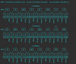
After looking at the data and remembering that the data is serially clocked into the TLC5940 most significant bit first (MSB), I decided that a picture might be worth a thousand words. With just one TLC, all the LEDs will be green. On the second TLC, all the LEDs with be blue, and the third TLC LEDs are red with the first line of DATA code.
I must apologize. Its been a while since I wrote the code and it took me a bit to remember how the data scheme worked, to optimize memory.
 

Attachments

elo31271

New Member
Ah yes the picture is totally making me understand the concept of 8 bit to 2-2bits. But why does 14=0,14 but 224=14,0? Am I missing a conversion chart or mathmatics somewhere? You have been over the top helpfull.
Thank you,
Elo
 

gbrusseau

Senior Member
Here's another picture to explain how one 8 bit word is divided into two 4 bit datagrams.

Binary 1110 = 14 decimal
8+4+2+0 = 14

Please don't take this wrong, but it sound like you could use a refresher in binary math.

By the way elo31271. Are you from Montana, USA
 

Attachments

elo31271

New Member
Ah yes, I needed a refresher, but thanks for the last image. It instantly made sence I now I understand. Thank you for sticking with me to get through this.

Nope, not from Montana, I am from Springfield, Missouri...
 

randomcows

New Member
Could someone post a quick diagram of how the circuit looks without the transistor rail, I don't need to do dot correction but I don't quite understand how to connect up the VPROG and DCPROG pins without the transistors. Would they still be connected from the TLC5940 to the PIC chip or just to GND and what would the pic chip pins be connected to (if anything)? Also, can they literally just be connected to ground or do they need a resistor or something?

Thanks in advance,
Mike
 

randomcows

New Member
Thanks

Simple as that? Great!

Thanks very much, that makes my life a lot easier. I'm making a similar circuit (but with a 28X1 and the PICAXE download circuits built in) using the laser printer/photo paper technique using a disposable acid etch in a bag system. My school isn't exactly well equipped for electronic projects ]: I can't do double sided PCBs with the equipment I have so there's going to be flying leads everywhere!

Many thanks,
Mike
 
Top