Buried wire sensor
- Thread starter Kiwi Bruv
- Start date
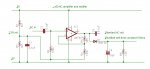
Attached circuit using a 741. The 2.5V reference has a low impedence of 4k7 and ideally one might use a dual op amp and and a voltage follower but this should work as it is driving 100k. The max resistance I have used in amps is 10M so start with 4M7, work backwards with a gain of 50 so that sets the other gain resistor at 100k. Then set the voltage reference resistors at least 10x less than this. The voltage ref resistors could be 1k to 10k but getting down to 1k the current starts to go up a bit.
The AC output resistor C3 is not strictly necessary but it could be useful as you could put your headphones on the output of the capacitor and listen to the tone. If the x50 is too much gain you will hear distortion in the tone. If so, then set the gain a bit lower.
The AC input goes to the output of your radio chip.
Do you have a CRO? It isn't strictly necessary but it might help with setting the gain. Listening to distortion will work almost as well. The DC output should vary from 2.5V to about 4V.
Attachments
-
 31.1 KB Views: 96
Last edited:
Buried wire detector
Hi Dr.
Built it tonight and it's working a treat. Strong pure tone at about 20 cm out. 2.2 V no tone to 2.9 V with tone. A couple of questions if I may.
Seems to be working out to about 80 cm from the wire. ADC value drops to 35 and inc to to 190 when right on the wire. How is this when the ADC input is 2.15 V min from the op amp? I expected the min adc10 values to be about 500 (approx half of 4.5V supplyV).
Up to 30 cm out it seems very reliable. Further out I am getting a few spurious ADC values occasionally. I can't hear the effect in the headphones but the ADC value goes either very low eg 15 or very high eg 230 What might be causing this?
I'll tidy it up a bit and do some testing to see if I can get a reliable relationship between distance, and ADC value.
Too excited!
Had to try some more. Mostly it works OK. There are 2 strange things happening.
1. When I went back and turned it on the ADC was 240, wire no where near the coil. On bringing the wire to the coil it dropped to 190 and behaved Ok from then on. Haven't been able to repeat it.
2. There seems to be a hot spot about 30 cm out and 10 cm below the coil. ADC jumps to 230, the software goes into a reversing sequence (no motors connected) and a beeper sounds, the ADC goes to 5. After the reverse sequence the software re-starts the forward motion and the ADC goes to 240. ADC value seems dependant on software state. Needs testing further but is quite strange.
Further out than 30 cm the detection works better (cleaner tone, further out) above the plane of the coil, below it's not as good, more static. The coil is mounted on the breadboard of the development board. Will the metal mass of the development board have an effect?
It seems to be working right out to 1 m, but is more unreliable until you get within 30 cm. This is Ok, as long as it doesn't spike over the "wire detected" threshold.
Not being familiar with radio. Will an antenna make it more reliable further out?
Last edited:
Sounds like you are moving ahead with quite a cutting edge project. The ADC readings seem odd - as you say it should be around 2.5V when no input (actually 2.5V- about 0.6V for the diode = 1.9V). Do the ADC readings agree with voltage measurements?
RF is a bit of a black art. Any bit of wire will act as an aerial, especially wire in coils. Any metal nearby will definitely change things - a metal cage round the whole contraption would block all RF (a Faraday cage). But some metal will act as an antenna and may increase sensitivity. At these frequencies an earth makes a big difference but for obvious reasons you can't really have an earth.
RF is a bit of a black art. Any bit of wire will act as an aerial, especially wire in coils. Any metal nearby will definitely change things - a metal cage round the whole contraption would block all RF (a Faraday cage). But some metal will act as an antenna and may increase sensitivity. At these frequencies an earth makes a big difference but for obvious reasons you can't really have an earth.
Last edited:
Buried wire detector
OK, sorry there is a lot to read here but something strange is happening. Appreciate any help.
On turn on the first ADC reading was always 254. Voltage was 2.1V. ADC should be more like 477 as I'm using readadc10.
I have a threshold set in the software of 200. With the transmitter off:
Upon starting ADC10 would be 254 (status part of program), software branches (goes to reverse routine) and reads ADC10 again, values of about 35, software returns to status and checks ADC10, values were > 200. So the ADC value oscillated back and forth with the software. All the time the voltage is 2.1V
I could break this cycle if I turned the transmitter on and brought it in range, the max readadc value was 196 and the voltage 2.9V. Min readadc was 35 and the voltage 2.1V. But after a random time but within a minute a value > 200 would occur even if the trans was turned off or out of range.
So I changed raised the threshold value to 300 to stop the software branching - ADc10 value would still be 254 on start and would remain above 200.
So I changed the readadc10 instruction to readadc . Now it's relatively stable. With the trans off it reads 103 to 130 with avge of 117. Which is about right for an output of 0.9 to 2.1V. It goes up to a max of 175.
Why doesn't readadc10 work? I really need the extra resolution. Modified Program is below. Can readadc10 and readadc be used in the same program? I was using readadc on adc 0, and readadc10 on adc 1. ADC 2 is tied to 0v with a 10K resistor.
'Mower program for 28x
'Inputs
'Input 0 is ADC for battery voltage
'Input 1 is ADC for right coil sensor
'Input 2 is ADC for left coil sensor
'Input 3 is spare ADC
symbol bump_sensor =pin0
' input pin 1 & pin 2 are reserved as pwm outputs
symbol tilt_sensor =pin4
'input 3 & 4 are reserved for i2C comm with LCD
symbol wet_sensor = pin5
symbol docked_sensor = pin6
' input 7 is spare
'Outputs
symbol piezo_sounder = 0
symbol cutter_motor = 1 'pwm output
'2 spare output/pwm
symbol right_motor_drive =4
symbol left_motor_drive = 5
symbol run_LED =6
'output 7 is serial comms with LCD
'Variables and constants
symbol full_charge = b0
Let full_charge =125 ' set battery threshold voltage for fully charged
symbol battery_value = b1
let battery_value =125
symbol running_flag =b13
symbol right_coil_proximity = b3
symbol left_coil_proximity = b4
symbol left_motor_speed = b5
symbol right_motor_speed =b6
symbol motor_speed_increment = b8
'Check machine status and if Ok goto start sequence
Status:
serout 7,N2400,(254,1) 'clear LCD
serout 7,N2400,(254,128) 'move cursor to start of first line
readadc 0,battery_value 'read battery voltage
let w5 = battery_value*100 'convert to integer in word range (0-65280)
let w5 = w5/106 'convert to integer voltage
'256 adc increments (0-255), full voltage = 24V, 1V = 255/24 = 10.625 adc values
'actual voltage to 1 dec place is adc value /106
'need to work out how to display with decimal on LCD
'serout 7,N2400, ("Power ",#w5 ," Volts")
'pause 1000
'serout 7,N2400,(254,128) 'move cursor to start of first line
'serout 7,N2400, ("Detecting Perimeter")
'pause 1000
readadc 1,right_coil_proximity 'check if perimeter detected
serout 7,N2400,(254,1) 'clear LCD
serout 7,N2400,(254,128) 'move cursor to start of first line
serout 7,N2400, ("Rgt prox ",#right_coil_proximity)
readadc 2,left_coil_proximity 'check if perimeter detected
serout 7,N2400,(254,192) 'move cursor to start of second line
serout 7,N2400, ("Lft prox ",#left_coil_proximity)
pause 1000
if right_coil_proximity >300 or left_coil_proximity > 300 then reverse_direction
' if perimeter detected turn around
if docked_sensor =1 then feed
if bump_sensor =1 then gosub reverse_direction 'obstacle, change direction
if tilt_sensor =1 then shutdown_mower
if wet_sensor =1 then home
if running_flag =0 then start 'if not already running goto start
if battery_value <full_charge then home
'sound piezo_sounder,(100,50) 'setup intermittent beep
goto status 'continue to monitor status
'Shutdown machine, wait and check status
Shutdown:
pwmout cutter_motor, 0, 0 'stop cutter (would be better to brake motor)
serout 7,N2400,(254,1) 'clear LCD
pause 30 'allow LCD to clear
serout 7,N2400,(254,128) 'move cursor to start of first line
serout 7,N2400, ("Stopping ")
Pulsout Right_Motor_drive,150 'stop (low outputs doesn't stop!) speed change on MD22 operates on next pulse
Pulsout Left_Motor_Drive,150
readadc10 0,battery_value 'read battery voltage
Pause 5000 'wait for complete shutdown
low run_LED 'turn off running lamp
Let running_flag=0 'flag start is required
sound piezo_sounder, (120,500)'signal stopped
serout 7,N2400,(254,1) 'clear LCD
pause 30 'allow LCD to clear
serout 7,N2400,(254,128) 'move cursor to start of first line
serout 7,N2400, ("Waiting for 1 min")
'put countdown here
sleep 25 'wait 1 min then check status
Goto status
'Terminate program
end_program:
serout 7,N2400,(254,1) 'clear LCD
pause 30 'allow LCD to clear
serout 7,N2400,(254,128) 'move cursor to start of first line
serout 7,N2400, ("Machine Stopped")
serout 7,N2400,(254,192) 'move cursor to start of second line
serout 7,N2400, ("Reset required ")
Sounder_Loop:
If b0 = 255 then Reset_tones 'check if tones are exhausted
Let b0 = b0+1 'increment tone
sound piezo_sounder, (b0,50) 'make sound
goto sounder_loop
Reset_tones:
Let b0=0 'reset tones from start.
goto sounder_loop
'Start operation
Start:
serout 7,N2400,(254,1) 'clear LCD
pause 30 'allow LCD to clear
serout 7,N2400,(254,128) 'move cursor to start of first line
serout 7,N2400, ("Starting Mower!")
'Sound Piezo_sounder, (100,500) 'signal start by sounding buzzer for 5s
Pause 5000 'wait 5s
Pulsout Left_motor_drive,180 'fwd motor
Let left_motor_speed = 180 'set motor speed variable
Pulsout Right_motor_drive,180
Let right_motor_speed = 180 'set motor speed variable
If wet_sensor = 1 then home ' if wet go home, don't start cutter
goto cutter_motor_on
Goto status
Cutter_motor_on:
pwmout cutter_motor, 9, 20
high run_LED
let running_flag = 1
goto status
Cutter_motor_off:
pwmout cutter_motor, 0, 0
low run_LED
let running_flag = 0
return
'reverse
reverse_direction:
pwmout cutter_motor, 0, 0 'stop cutters
low run_LED
let running_flag = 0 'ensure start is required
Pulsout Right_Motor_drive,150 'stop (low outputs doesn't stop!) speed change on MD22 operates on next pulse
Pulsout Left_Motor_Drive,150
Pause 1000 'wait 1s for drives to stop
serout 7,N2400,(254,1) 'clear LCD
pause 30 'allow LCD to clear
serout 7,N2400,(254,128) 'move cursor to start of first line
serout 7,N2400, ("Reversing ")
Pulsout Right_Motor_drive,100 'reverse
Pulsout Left_Motor_Drive,100
pause 3000 'reverse for 3s, assumes no obstacles in rear!!!
'Change_Direction right turn approx 180 deg
serout 7,N2400,(254,1) 'clear LCD
pause 30 'allow LCD to clear
serout 7,N2400,(254,128) 'move cursor to start of first line
serout 7,N2400, ("Change Direction")
Pulsout Right_motor_drive,125 'rev right motor
Pulsout Left_motor_drive,175 'fwd left motor
Pause 1500 ' turn for 3s
Pulsout Right_Motor_drive,150 'stop (low outputs doesn't stop!) speed change on MD22 operates on next pulse
Pulsout Left_Motor_Drive,150
Pause 1000 'wait 1s for drives to stop
Pulsout Left_motor_drive,180 'fwd motor
Pulsout Right_motor_drive,180
goto status
'Find way home
home:
'continue until perimeter detected then follow wire routine ignoring
' perimeter detector until docked nb this mows the edges., then go to charging state
serout 7,N2400,(254,1) 'clear LCD
pause 30 'allow LCD to clear
serout 7,N2400,(254,128) 'move cursor to start of first line
serout 7,N2400, ("Going Home ")
'Put wire following routine here.
readadc10 1,right_coil_proximity
readadc10 2,left_coil_proximity
let motor_speed_increment = 5
' set motor to run 20% faster then default forward speed when turning
' 100 is full rev, 150 is off, 200 is full forward but 175 is right setting
' for wheel diameter and motor speed so the available range of forward speed
' increments is 175 -150 = 25.
if right_coil_proximity > left_coil_proximity then gosub left
'right coil is closer to wire, turn left
if right_coil_proximity < left_coil_proximity then gosub right
'left coil is closer to wire, turn right
if bump_sensor =1 then shutdown_mower 'stop cutter and stop
if docked_sensor =1 then shutdown_mower 'arrived
sound piezo_sounder, (120,75) 'make homing sound
goto home 'continue to monitor status
left:
serout 7,N2400,(254,192) 'move cursor to start of second line
serout 7,N2400, ("Turning Left")
let b7 = left_motor_speed + motor_speed_increment
pulsout left_motor_drive, b7 'turn right wheel faster than left
pause 1000
pulsout left_motor_drive,175 'reset motor speed to default
let b7 = left_motor_speed - motor_speed_increment
return
right:
serout 7,N2400,(254,192) 'move cursor to start of second line
serout 7,N2400, ("Turning Right")
let b7 = right_motor_speed + motor_speed_increment
pulsout right_motor_drive, b7 'turn right wheel faster than left
pause 1000
pulsout right_motor_drive,175 'reset motor speed to default
let b7 = right_motor_speed - motor_speed_increment
return
'
Gonna need some input from all the brains trust on this one!
Readadc10 should not be doing that. Need to simplify things and do a few experiments. What happens if you just have a pot - 0V - wiper - 5V and feed the wiper into the analog input and use a short bit of code - pause 1000, readadc10, debug, repeat. If that doesn't work then ? the pin is zapped. If it does work, try bringing RF up nearby and see if it changes things. If so, need to look at RF shielding for some parts of the circuit (essentially a metal box. Any old steel can will do. ).
Readadc10 should not be doing that. Need to simplify things and do a few experiments. What happens if you just have a pot - 0V - wiper - 5V and feed the wiper into the analog input and use a short bit of code - pause 1000, readadc10, debug, repeat. If that doesn't work then ? the pin is zapped. If it does work, try bringing RF up nearby and see if it changes things. If so, need to look at RF shielding for some parts of the circuit (essentially a metal box. Any old steel can will do. ).
You have used byte variables (b1, b3, b4 etc) for the ADC results - these can only store a number between 0-255, so cannot be used with a readadc10 command but will work with readadc. That is why you get the strange overflow reponses.
You must change your variables to word variables (w3, w4 etc instead).
You must change your variables to word variables (w3, w4 etc instead).
Thankyou all.
It's working very well.
490 adc value with no tone, or wire at 80 cm, 700 adc with the wire directly over the coil.
+/- 30 adc values at long range but rock solid at less then 20 cm.
Next step is to build the other half of the sensor and see if it can follow the wire.
It's working very well.
490 adc value with no tone, or wire at 80 cm, 700 adc with the wire directly over the coil.
+/- 30 adc values at long range but rock solid at less then 20 cm.
Next step is to build the other half of the sensor and see if it can follow the wire.
Hi Kiwi Bruv, Not sure if you are still working on this, but I would like to know how it is working.Thankyou all.
It's working very well.
490 adc value with no tone, or wire at 80 cm, 700 adc with the wire directly over the coil.
+/- 30 adc values at long range but rock solid at less then 20 cm.
Next step is to build the other half of the sensor and see if it can follow the wire.