Buried wire sensor

Kiwi Bruv

Member
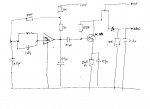
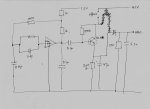
I am building a wire guided robot. I have a transmitter based on an oscillator currently running at 80kHz on the wire. With suitable choice of coil & cap and inc my oscillator to 150Khz or greater can I use the MK484 radio Ic chip to tune into the signal in the wire, amplify it using a transistor, and use a comparator on two such circuits to control my robot?

I want to do this this way because I am not experienced enough with analogue electronics and this chip gives me detection, amplification and gain control.

http://www.rapidonline.com/resources/docs/82-1026.pdf

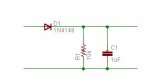
Transmitter power is 120 mA at 50% duty cycle and 12 V. I can tweak as required.
I am OK with using op amps to amplify the signal but using op amps I can only find the wire at about 5cm. Increasing power isn't an efficient or elegant way to improve detection range because of the inverse sq rule. So I want to increase sensitivity 6 fold by using an off the shelf package like the MK484.

I need to detect the wire at about 30 cm distance and use the signal strength to follow the wire with a two sensors a la a line following robot.

I am a bit confused about how the sensitivity of the detector. Will the proximity to the wire be the RMS voltage output of the IC (op amp or Mk484)? If the IC tunes in to my signal will it be the same RMS output at 30 cm and 5 cm? If so how do I measure proximity?

Will a simple inductor be OK or do I need the full ferrite rod arrangement?
 

Rickharris

Senior Member
Why buried wire?
Extract from patent for such a system " A wire guidance system for a materials handling vehicle, such as a turret stockpicker, detects an alternating signal carried by a buried wire. Two sets of four sensors each are carried at either end of the vehicle. The distance and angle of the vehicle is determined by reference to the distance measurements of each sensor set, as calculated by a microcomputer. Deviations in the angle or speed from predetermined limits will cause brakes to be applied and require operator intervention before the vehicle can be restarted."

more" [FONT=Arial, Helvetica, sans-serif]The intelliguide system has a wire buried in the floor 1/2" 5/8" deep in the center of each storage aisle that transmits an electrical signal which is received by a sensor on the truck. A line driver energizes the wire at 5.2 or 6.25 KHz. The sensors on the truck acknowledge the signal from the wire and control the steering mechanism to enable the truck to follow the wire automatically. The wire guidance system is integrated with the truck's braking system so that if the signal is lost the truck will automatically slow down and stop."

An E book
[/FONT]http://books.google.com/books?id=wWzGAff3sqkC&pg=PT785&lpg=PT785&dq=buried+wire+guidance&source=web&ots=R1Ki-67noQ&sig=QWacDZf6lXGJCfp0wOWgI-npymw

Another E document "http://www.frog.nl/agv-technology.php"


I would think you could pick up the signal but making the robot understand where it is may be different - e.g. how would you know which side you are on - left or right?

The signal will propagate quite a long way or at least be picked up a long way away as this IC is intended for commercial radio reception.

Lastly if your in the UK you may interfere with commercial radio transmission (a big no no)
 

demonicpicaxeguy

Senior Member
whats the surface type?

if it concrete you could always paint two highly contrasting colors (white and black/green) and make use of a few photo detectors

it would be safer and more reliable, also if you're adventurous you could use different color lines as a guide for thigs like automated forklifts
 

moxhamj

New Member
I have played around with circuits at 1Mhz. On the old AM dial that is 1000 Khz which is in about the middle of the dial. It is quite helpful to hear the tone on an ordinary radio (or indeed, a crystal set). A 1Mhz oscillator can be built using a 74HC04 and an xtal and a transistor to boost the signal and you can turn it on and off at 1khz using a picaxe to generate a tone. I agree it makes sense to put the minimum power into the driver circuit (it might even be solar powered), so the clever part is in the receiver.

At these sorts of frequencies an antenna is about 70 metres long but a robot trailing 70 metres of wire is a bit impractical. The solutions are all the same solutions used in AM radios and the usual one is to use a ferrite rod with wire wound around it. Ferrite rods and associated tuning capacitors for the AM band 800Khz to 1.6Mhz are easily and cheaply available from electronics stores so it makes sense to use commercial ones rather than trying to wind your own. Or you could get a radio kit (crystal or transistor) or even just use an AM radio. It probably is easier to just use a radio as everything is optimised and the output is an audio signal. Indeed, with a radio the biggest problem might be over sensitivity but you can always decrease the power to the wire round the garden until it is optimised.

The transmitter doesn't have to be exactly 1Mhz but at least with a locked frequency it is a simple matter to look up radio stations in the area and see if any are transmitting at 1000Khz. Or just tune a dial on a radio to that point. If the wire is buried and you are putting less than a watt into it then the range might be only a few tens of metres.

The one big variable that would need experimentation is what happens in dry soil vs wet soil.
 
Last edited:

Kiwi Bruv

Member
Buried wire detector

Thanks Dr.

That has got me thinking. My original idea was to have the robot detect the electromagnetic field in the wire, so no need for a tone. But a tone would make it more specific and greatly assist troubleshooting and the radio solution is a good one for me as I prefer to bolt it all together and enjoy the programming part more than the build part.

Also I was wanting a way of switching the robot track from the lawn edge to following a line to a solar recharging station. I guess I could do that on a wire using a different tone.

I know nothing of tones and radio so how would I use a picaxe to generate a tone? I am using LTC1799 for the oscillator so it can do 1MHz allright.
 

moxhamj

New Member
Picaxes are great for tones. Have a look at the Sound commands in the menu. The sound goes for a few seconds so just keep looping through for a continuous tone.

Or an almost wasteful use of a picaxe but I have done it before;
main: high 1
pause 1
low 1
pause 1
goto main

=500hz - about B above middle C

You could run the 1Mhz from the LTC1799 and the tone from the picaxe through an AND gate, but an even simpler solution would be to run the power to the LTC1799 from the pin on the picaxe that is generating the tone. Say the picaxe is running at 1khz then it will go high for 0.001 seconds, the LTC1799 will produce about 1000 pulses (at 1Mhz) then the picaxe pin will go low for 0.001 seconds. I couldn't find the power specs for the LTC1799 but it should come in under the 20mA max for a picaxe pin. addit - found it and is only 1mA so this would work.

It probably doesn't really matter what the frequency of the Sound command is as they all come in within the audio range.

Poor man's speaker to hear the sound coming out of a picaxe pin - just get any old speaker 4 ohm/8 ohm/32ohm headphones and put in series with a 220 ohm resistor.

I've always wanted to build one of these robots. I have one half completed from 15 years ago and the brains were always the problem so picaxe might help finish that project. I had the idea of making it solar powered maybe with a 10 watt panel. The hard part is calculating the energy in and the energy out so the robot maybe sits still for an hour charging (ideally it can find a sunny spot by itself) and then wander round for 10 minutes once it is charged. That is the part that picaxe can do so well as it is really hard to do with discrete logic and PCs/computers use too much power.

With bandpass filters you could certainly have it following different wires with different tones. You can easily rectify an AC signal with a diode and then a resistor/capacitor or a slightly more complex and more perfect AC to DC converter using an op amp.
 
Last edited:

eclectic

Moderator
Just Picaxe?

To Dr A and Kiwi.

How about using the Picaxe as both oscillator and modulator?
I've just been playing with an 08 protoboard and a scanner set on 1MHz.

setfreq m8
main:
pwmout 2 ,1,4
pause 1
pwmout 2,0,0
pause 1
goto main

Using about 500 cm of hookup wire from pin 2, I could easily detect a tone at 2 metres.

Then I tried outside, with about 10 metres of wire laid flat. Detectable at c. 20 cm.
(Too cold to run further tests!)

e.
 

moxhamj

New Member
What a brilliant suggestion Eclectic - that gets it down to one chip. Were you getting the range with direct drive from the picaxe (20mA?) or with a transistor amplifier?

If it is direct drive then at most the picaxe is drawing 0.02A*5V=0.1W which means the wire loop driver could easily be solar powered.

A standard AM radio usually has a headphone jack so that can be the audio output. A 914 diode into a 10k and 1uF next to each other as a low pass filter plus rectifier and measure the volts, which should change as the volume of the tone changes on the radio. Then feed that voltage into an ADC on a picaxe. The volume knob on the radio can be used to adjust the sensitivity.
 

Attachments

Last edited:

moxhamj

New Member
PWMout 2,0,0 does turn it off - for 1 millisecond which is the pause 1 right after it.

So it is on at 1Mhz for 1 millisecond then off for 1 millisecond. Perfect for creating a 500Hz tone that can be heard on an AM radio.
 

Kiwi Bruv

Member
Buried wire detector

Got it. Period is 2mS so Freq is 500 Hz. Very clever. I've learned about PWMOut and a lot more.

This has been an immense help. Many Thanks. I've dug out an old Walkman radio and will give it a go tomorrow.
 

eclectic

Moderator
To Dr A and Kiwi.

Sorry for the time-zone delays.

Quote

Were you getting the range with direct drive from the picaxe (20mA?) or with a transistor amplifier?


The transmitter antenna was a simple length of wire, attached directly to Picaxe pin 2.
Power was 4 x NiMh.

Some tests for me to try later are;
1.Current used.
2.Effect of feeder cable. (RG58)
3.Harmonic output.

As an aside, if the scanner were calibrated, then this technique
could be used to test the processor speed of the Picaxe.

e.
 

Kiwi Bruv

Member
Success

Hooked it up tonight with a bit of tweaking. My 28x has a 4 mHz external resonator so at first I couldn't work out why it wasn't working. It was because at 1MHz the wizard was suggesting a period of 0 which turns the PWMOUT command off.

So I proved the PWMOUt pin was working with some other values and then reduced the frequency until the period was 1 and hey presto.

My walkman radio picked the signal up at 585 - 600 kHz and my DMM said it the tone was at 238.5 Hz. This was straight out of the pin into a few loops of wire, detectable at about 20 cm.

Will put it through a transistor tomorrow to see if I can get it out another 10 cm or so and then into the picaxe ADC

I will probably upgrade my axe or resonator to get it at 1MHz, but if I don't does the 10K and 1uF conditioning for the ADc input need to change?

Very pleasing thanks very much.
 

moxhamj

New Member
Sounds like this is working very well. The 10k/1uF are just a filter to change the response time so it takes a second or two to change. You can certainly decrease the C value to make it respond quicker. The RF frequency isn't that important so long as it comes somewhere in the AM band and also doesn't happen to be the same frequency as a radio station.
 

Kiwi Bruv

Member
Buried wire detector

http://www.rapidonline.com/resources/docs/82-1026.pdf

Constructed the circuit above using the MK484 and the result is exceptional. The tone is now detected at approx 1 m. Using just the picaxe at 50% duty cycle (7mA) or a transistor (32mA) doesn't seem to make much difference. I think the detector coil size and the MK484 vs my old walkman radio receiver must make a bigger difference.

So now it's a bit too successful, how do I put a volume control on the above circuit to reduce the sensitivity? Is it just a question of controlling the gain of the transistor? Will a liner pot do?
 

eclectic

Moderator
Detection distance.

KiwiBruv. Great work so far.

Is the one metre detection distance "on the bench",
or is it from say 20 metres of wire laid flat (or even buried)?

e.
 

Kiwi Bruv

Member
How to decrease detector coil size.

My coil is a 100mm ferrite rod and "broadcast quality" winding. It's a bit big and now the principle is proven I'd like to replace it with an inductor that is both smaller and easier to fix the direction of.

At 1 mHz I could tune the circuit with a 10mH inductor and a 2.53 pF cap.

I can buy this combo with a variable cap to tune in my tone but will it work? Plus the components are described as chokes and inductors and sometime RF inductors. Which should I buy?
 

Kiwi Bruv

Member
Buried wire detector

Detection distance is "on the bench". About a 1m loop draped over the end of the bench. So it's a vertical flat wire, if that makes sense?
 

eclectic

Moderator
Outside tests.

When I did my first, very quick, tests, I used a very sensitive (and expensive)
scanner radio. Bench = > 2 metres. Outside, with long wire ~ 20 cm.

Might I suggest, before anything else, that you do some longwire tests,
on or preferably under, your soil.

e.
 

moxhamj

New Member
Re "So now it's a bit too successful", yes I'd try burying the wire now as I think it will decrease the sensitivity a lot. Maybe try in dry soil, then try watering the soil. There are still ways to turn the sensitivity up or down depending on how this experiment turns out.
 

Kiwi Bruv

Member
Buried wire detector

Thanks guys.

I put 20 m of 1.5mm2 wire around the garage floor in a big loop.

At ground level the signal is detectable at about 80 cm. 10cm off the floor the signal is detectable at 20cm, at 30 cm of the floor the signal strength comes back to about 50cm and at waist height the signal is very strong again.

So I see the field strength depends on the material around the wire quite a lot.

One option is to pin the wire to the top of the lawn rather than burying it. I need to make the trans and detector more robust and get an 08M and prototype board so it may be a week or so until I post again.

My robot chassis is about 10cm of the ground so the signal reduction at the 20cm level might be an issue or might be just about right.
 

demonicpicaxeguy

Senior Member
i had a though on this topic which might be a better way to go,
just use a hall effect sensor and a line of buried rare earth magnets all you'de need to do is push a spike into the ground and drop a magnet in, to stop corrosion coat them in somekind of plastic or casting resin, maybe spray them with laquer

you may even ben able to get away with a reed switch if it's sensitive enough,

it'd would also save the lawn from having to recover from the wire installation
 

Kiwi Bruv

Member
Buried wire detector

Good idea, it would simplfy things. But I think you would need a magnet every 5 - 10 cm and the sensor would need to be quite close at ground level in the grass.

What do you think the space between the magnets would need to be and the distance the hall effect sensor would work at?
 

Rookie

Member
casing magnets...

One interesting thing... maybe will be a good idea "chain-up" the magnets to one fishing line, that way you'll be able to recover from the ground soil.
or glue it over one golf spike and put it on soil level.
Some magnets come plastic coated (fridge, or news-board type).

From the web:
"...
In case of a current-carrying wire, the sensor underneath the AGV(Automated Guided Vehicle) is usually a small antennae consisting of magnetic coils. With current flowing, a magnetic field surrounds the buried wire. The closer the buried wire is to the AGV antennae, the stronger the field. The magnetic field is completely symmetrical around the conductor or the buried wire. At a given distance from the wire the field has the same strength on either side of the cable. The field strength is detected by the antennae's magnetic coil and induces voltage in the coil.

The Automated Guided Vehicle steers itself to follow the magnetic field surrounding the buried wire. To get a steering correction signal the AGV's sensing antennae consists of two coils. When the vehicle is centered directly above the buried wires equal voltages are induced in the two coils. If the Automated Guided Vehicle moves a bit to one side of the wires, the induced voltages would be of different strength. The difference in signal strength in the coils is proportional to side displacement of the coil. This difference is amplified and fed back to control an onboard servo motor, which turns the guide wheel or wheels until both coils receive equal signals, and the course is corrected.
..."
 
Last edited:

ljg

New Member
a little late to this, but it might help.

have you looked at the Robocut.se site?
This was a lawn mower project using a Basic Stamp that was to be sold as a kit. apparently the lawyers got hold of the developers and ended the project, but there's still lots of information on line, including schematics and formulas for the buried wire part of the project.

Here's a link to the English portion of the site. spend a couple hours following the links- it's well worth following the Swedish parts, too.

Look at the videos for inspiration while you are at it. It's a shame the project never came to fruition.

Robocut English
 

Attachments

Last edited:

Kiwi Bruv

Member
Buried wire detector

Yes I found the swedish site whilst researching for my project but I lack the expertise and equipment to build and test the detector part. I have had a couple of goes and I just can't make it sensitive enough.

Hence the suggestion of the radio option which is working out well so far.

Thanks for the interest.
 

Kiwi Bruv

Member
Ok, I took my bot for a drive on the grass and burned up the plastic gearboxes. So now I have some metal gearboxes and so I'm back.

My sensor is detecting the wire, but barely.

Audibly the signal is strong and varies the closer the bot to the wire. The tone is at 483Hz. The sound is noticably louder if the wire is about 10 cm off the floor which is the height of the coil.

The ADC10 signal is between 170 and 196 with no signal. If the bot is over the wire the signal goes to 208. I have used Dr Aculas signal conditioning with a small diode, on the radio output, feeding into a 10K res and a 2.2nF cap in parallel.

I am using the picaxe as a direct drive into the wire as when I used a transistor and the headphones using a transistor to boost the power disn't seem to do much.

What do I need to do get a better range signal into the picaxe?
 

Kiwi Bruv

Member
Ok I take it back.

It seems to be just a coincidence the ADC10 threshold I set for the software to react was 200, so the bot was behaving Ok but when I turned of the transmitter for a bit the bot sometimes still reacted.

My DMM says the voltage at the +ve terminal of the cap (ADc input) is 0.795V which is suspiciously close to the voltage drop across the diode.

If I tune the radio into a station or my transmitter the voltage here doesn't change.

So it seems I can hear the signal but not detect it with the picaxe.

Help please.
 

moxhamj

New Member
There are lots of circuits that would work (op amps, filters, op amp rectifiers that null out the diode voltage drop) but it would be great to do this with the minimum components. If you can hear a tone when it is close then it should be possible to detect this. A very quick test - do you have an AC voltage setting on the DMM? If so, measure the AC volts coming out of the radio with the tone and without the tone. Those readings may help determine what sort of signal conditioning is needed.
 

Kiwi Bruv

Member
Buried wire detector

Hi Dr.

Thanks for the help.

I had the radio output powered by the radio Ic circuit (only 1.5V), so fixed that and it made everything louder.

Still Results are only 0.16V with the tone, 0.08 V without it.

Plus the 0.16V drops to 0.08V when the software detects the wire (adc10>200) and changes the pic outputs. Even with power to motors and motor driver off. ie picaxe is the only thing running. The only outputs that change are a single pulse out on 2 pins (used to tell the motor driver what to do) and a pulsout to a piezo. Can the output to the piezo be causing this. I will take it out and check.

Audio tone is loud enough for me to hear it when headphones are a metre or so away. So strong tone but not much getting to the picaxe input.
 

Attachments

Last edited:

moxhamj

New Member
That schematic doesn't look quite right. The diode is being driven directly off the 4.5V. ? needs to be driven off the emitter of the transistor.

I'd be interested in the AC readings between the emitter of the transistor and ground.
 

Kiwi Bruv

Member
Buried wire detector

Corrected schematic attached.

Measurements are:

At emitter 0.015V tone on, 0.05V tone off

At ADC input 0.012v tone on, 0.05V tone off

ADC10 reads approx 150 and doesn't change with tone on or off.

ADC channel 0 is connected to a pot and works OK
ADC channel 1 is the sensor and reads 150
ADC channel 2 is not wired and reads 163
 

Attachments

moxhamj

New Member
Are those voltage readings on the AC or DC range? They seem very low considering you can hear a tone. Are you using a piezo speaker or an ordinary 8 ohm speaker? I suspect the signal needs amplifying and a simple audio amp would work. You could build one out of an op amp or an amplifier chip, but it may be even simpler to use a cheap AM radio that has a small speaker, and just hack into the drive to the speaker. How are your skills with amplifiers and do you have any op amps lying around?
 

Kiwi Bruv

Member
Buried wire Sensor

AC readings

I am using my headphones from an old walkman, not sure what resistance.

I am using the MK484 solution exactly as

http://www.rapidonline.com/resources/docs/82-1026.pdf

except I am supplying the chip through a 3 x 100 ohm potential divider from the 4.5V picaxe supply and the output transistor amp is supplied with the 4.5V.

it's a one chip radio solution, capable of driving a 32 ohm speaker through a transistor.

I can hear radio stations and the tone OK. I have some op amps but surely this should work?

If don't understand if I can hear the tone loudly in the headphones, why is the emitter voltage so low? What could cause this. A breadboard defect or component defect?

I'll measure the MK484 ac voltage output as the pdf file says it should be 40 -60 mV which is lower than my emitter readings and would imply the transistor amp isn't working. But if I can hear tones and radio stations the chip and transistor amp must be working.

Would appreciate it if you could check out the MK484 circuit and specs above and see if I have done something wrong.
 

moxhamj

New Member
Ah, that makes sense. I looked at the schematic for the radio chip and compared it with yours. The headphones are 32 ohms. The transistor driver circuit is specifically designed for driving headphones and isn't really the circuit for producing volts.

If you took the output from the chip directly it would be 40mV. That won't register much on readadc10. A gain of 100 will give 4Vand maybe to play it safe make it a gain of 50 to give 2V. You can leave the circuit exactly as it is for listening to the tones, and add the amplifier to the output of the chip. You need an AC amplifier with a gain of 50 and a relatively high impedance. I'll get out my op-amp recipe book when I get home tonight and draw up a circuit. What op amps do you have?
 
Top