procfanousek
Member
Hello everybody,
I would like to share simple robot with 08M2 and ultra simple H-bridge. Credit for H-bridge goes to Mr. Andrew H.:
http://www.brightsparks.org.nz/the-forum/bb-our-main-discussion-forum-come-in-here/h-bridge-16842/
http://www.brightsparks.org.nz/the-forum/bb-our-main-discussion-forum-come-in-here/-24688/
http://www.brightsparks.org.nz/the-forum/heeeeelllllllpppppp-im-confused-look-in-here-for-help-or-just-ask/how-to-switch-on-and-off--16804/
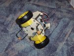
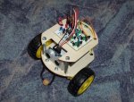
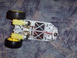
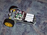
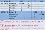
Only two pins control directions of two motors. Each motor has its own H-bridge. Log 1 - motor forward, Log 0 - motor backward, Input - motor stops. I use "yellow motors" that starting running at 3V and take about 190mA. For such a h-bridge to function it is important to use low voltage and low current motors. Do not forget to put ceramic capacitor directly across motor terminals. I use 4 x AA NiMh 1,2V batteries to eliminate voltage drops. The robot runs very well. There is one more pin left that can be used for IR control. Attached you can find KiCAD files for inspiration. The base of robot is made of plywood. To make it cheap I used what I found at home. The front and rear supports are made of solid Cu wire with cross-section 2,5mm and wooden beads.
EDIT: the links are dead, because there is a new forum. But there is this post at least:
https://forums.brightsparks.org.nz/viewtopic.php?f=10&t=47
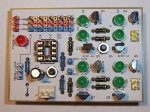
EDIT 2: I changed schematic. I added IR sensor that is connected to the pin c.5 (see this discussion http://www.picaxeforum.co.uk/showthread.php?30033-08M2-No-reset-pin/page3) and changed the value of "programming resistors" accordingly. There is also a PWM circuit in the schematic (credit goes to Andrew form brightsparks forum). The pcb has pin headers for easy change of connections between various parts of the whole circuit. In the zip file there is schematic and PWM circuit with H-bridge. This is the reason for a jumper at GND branch of the H-bridge. There are also two leds and a buzzer for various experiments with the Kolobot.
View attachment KiCAD.zip
I would like to share simple robot with 08M2 and ultra simple H-bridge. Credit for H-bridge goes to Mr. Andrew H.:
http://www.brightsparks.org.nz/the-forum/bb-our-main-discussion-forum-come-in-here/h-bridge-16842/
http://www.brightsparks.org.nz/the-forum/bb-our-main-discussion-forum-come-in-here/-24688/
http://www.brightsparks.org.nz/the-forum/heeeeelllllllpppppp-im-confused-look-in-here-for-help-or-just-ask/how-to-switch-on-and-off--16804/
Only two pins control directions of two motors. Each motor has its own H-bridge. Log 1 - motor forward, Log 0 - motor backward, Input - motor stops. I use "yellow motors" that starting running at 3V and take about 190mA. For such a h-bridge to function it is important to use low voltage and low current motors. Do not forget to put ceramic capacitor directly across motor terminals. I use 4 x AA NiMh 1,2V batteries to eliminate voltage drops. The robot runs very well. There is one more pin left that can be used for IR control. Attached you can find KiCAD files for inspiration. The base of robot is made of plywood. To make it cheap I used what I found at home. The front and rear supports are made of solid Cu wire with cross-section 2,5mm and wooden beads.
EDIT: the links are dead, because there is a new forum. But there is this post at least:
https://forums.brightsparks.org.nz/viewtopic.php?f=10&t=47
EDIT 2: I changed schematic. I added IR sensor that is connected to the pin c.5 (see this discussion http://www.picaxeforum.co.uk/showthread.php?30033-08M2-No-reset-pin/page3) and changed the value of "programming resistors" accordingly. There is also a PWM circuit in the schematic (credit goes to Andrew form brightsparks forum). The pcb has pin headers for easy change of connections between various parts of the whole circuit. In the zip file there is schematic and PWM circuit with H-bridge. This is the reason for a jumper at GND branch of the H-bridge. There are also two leds and a buzzer for various experiments with the Kolobot.
View attachment KiCAD.zip
Last edited: