Hairy Animal
Member
Experimenting recently with one of the little (approx. 1"/26mm sq.) DS1307 Real Time Clock (RTC) boards with EEPROM (AT24C32, 4096 bytes), I needed a bit more detail as the majority of sellers on a well known auction site don't seem to offer much if any detail. Even where there is more detail, some descriptions are erroneous, describing the EEPROM for instance as 8192 bytes.
It didn't take long to discover a circuit diagram on an electronics hobby website but even that wasn't 100% accurate, so I hoped it might be useful to other PicAxe users if I posted what I've discovered here. I've since discovered another circuit diagram in other posts on this forum, which also doesn't appear to be wholly accurate.
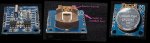
Being a bit impulsive, I'd already tried installing a standard CR2032 coin cell in the battery holder on the back of the board, to see if the RTC continued to run properly when I turned the power off. It didn't work and, I discovered, the battery was getting warm. I then discovered that there was a bent tab in the battery holder which was shorting the battery (see the battery holder photo). Once unbent, things looked better, but the battery voltage then rose well above the nominal 3.2V it was supposed to be. Time I found the circuit diagram.
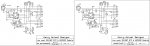
Once I'd discovered a circuit diagram, all became clear - the circuit is designed for a rechargeable 3.6V (LiR2032) and to use it with a standard CR2032 cell requires some modifications. The diagram I found suggested removing R4, R5, R6 & D1, replacing R6 with 0 ohms i.e. a bit of wire. I didn't see any point in removing R5 as it's in series with D1, so once that's out R5 doesn't connect to anything. R6 also can be bypassed with a bit of wire without the need to remove it. This then connects the CR2032 directly to the DS1307. R4 must be removed though, otherwise it just drains the battery.
D1 must be removed to avoid trying to charge a battery which isn't designed to be charged - potentially it could catch fire or even explode, though mine didn't even when left for several hours before I realised what was happening. I wouldn't recommend it though!
The attached picture of the component side shows R4 & D1 removed and the R6 bypass link. Before & after circuit diagrams are also attached. The component values are correct according to what I can see from photos on the well known auction site and my own board (not sure about C1 & C2 but it's more likely that they are 100nF rather than 100pF).
Something else I gleaned from the original circuit diagram was that the unoccupied U3 location is designed for the ubiquitous DS18B20 digital thermometer, for which of course PicAxes have a built-in read command (READTEMP/READTEMP12). However the original circuit diagram suggested the board didn't have the required pullup resistor. Wrong, it does, it's R1 but it's 3k3 instead of the recommended 4k7.
The I²C* pullups are also 3k3 instead of 4k7, but the I²C bus seems to work perfectly well as does the DS18B20 I fitted (but it might not if 4k7 pullups were also fitted on the PicAxe board). Note also that the SQ output from the DS1307 has a 3k3 pullup fitted as well which might well be a suitable current source for an LED to show seconds (this output can also be directly controlled via register bits).
The photo with the battery in place shows the position (top right) for the DS18B20 which is fitted on this side as the device outline shows.
At about 41p (at 5x) for this useful board, a 48p DS18B20 (10x) and a 20p CR2032 (5x) battery together with a PicAxe 08M2+, you've got the basis for a remarkably cheap, and tiny, data logger which can store, for instance, four 1-byte values once a day for more than three years and nine months.
* - Pedant mode, it's I²C (for IIC or Inter-Integrated Circuit bus), not 12C (as on the board) nor I2C (though I accept that not all systems can reproduce the ² character).
Note to moderators - if a different forum is more appropriate, please feel free to move this post.
It didn't take long to discover a circuit diagram on an electronics hobby website but even that wasn't 100% accurate, so I hoped it might be useful to other PicAxe users if I posted what I've discovered here. I've since discovered another circuit diagram in other posts on this forum, which also doesn't appear to be wholly accurate.
Being a bit impulsive, I'd already tried installing a standard CR2032 coin cell in the battery holder on the back of the board, to see if the RTC continued to run properly when I turned the power off. It didn't work and, I discovered, the battery was getting warm. I then discovered that there was a bent tab in the battery holder which was shorting the battery (see the battery holder photo). Once unbent, things looked better, but the battery voltage then rose well above the nominal 3.2V it was supposed to be. Time I found the circuit diagram.
Once I'd discovered a circuit diagram, all became clear - the circuit is designed for a rechargeable 3.6V (LiR2032) and to use it with a standard CR2032 cell requires some modifications. The diagram I found suggested removing R4, R5, R6 & D1, replacing R6 with 0 ohms i.e. a bit of wire. I didn't see any point in removing R5 as it's in series with D1, so once that's out R5 doesn't connect to anything. R6 also can be bypassed with a bit of wire without the need to remove it. This then connects the CR2032 directly to the DS1307. R4 must be removed though, otherwise it just drains the battery.
D1 must be removed to avoid trying to charge a battery which isn't designed to be charged - potentially it could catch fire or even explode, though mine didn't even when left for several hours before I realised what was happening. I wouldn't recommend it though!
The attached picture of the component side shows R4 & D1 removed and the R6 bypass link. Before & after circuit diagrams are also attached. The component values are correct according to what I can see from photos on the well known auction site and my own board (not sure about C1 & C2 but it's more likely that they are 100nF rather than 100pF).
Something else I gleaned from the original circuit diagram was that the unoccupied U3 location is designed for the ubiquitous DS18B20 digital thermometer, for which of course PicAxes have a built-in read command (READTEMP/READTEMP12). However the original circuit diagram suggested the board didn't have the required pullup resistor. Wrong, it does, it's R1 but it's 3k3 instead of the recommended 4k7.
The I²C* pullups are also 3k3 instead of 4k7, but the I²C bus seems to work perfectly well as does the DS18B20 I fitted (but it might not if 4k7 pullups were also fitted on the PicAxe board). Note also that the SQ output from the DS1307 has a 3k3 pullup fitted as well which might well be a suitable current source for an LED to show seconds (this output can also be directly controlled via register bits).
The photo with the battery in place shows the position (top right) for the DS18B20 which is fitted on this side as the device outline shows.
At about 41p (at 5x) for this useful board, a 48p DS18B20 (10x) and a 20p CR2032 (5x) battery together with a PicAxe 08M2+, you've got the basis for a remarkably cheap, and tiny, data logger which can store, for instance, four 1-byte values once a day for more than three years and nine months.
* - Pedant mode, it's I²C (for IIC or Inter-Integrated Circuit bus), not 12C (as on the board) nor I2C (though I accept that not all systems can reproduce the ² character).
Note to moderators - if a different forum is more appropriate, please feel free to move this post.
")