TLV493D-A1B6 3D Magnetic Sensor
- Thread starter edmunds
- Start date
Apart from an ACK issue it seems the receiver returns $00 which is better than it was using HI2CIN.
Seems I got who generates the ACK wrong earlier. It's always the receiver who generates the ACK so -
So, E&OE ...
Added: Found an ambiguity in the data sheets ...
Read Register 7 : Bits 6:3 must be written into register 1 in case of write.
Write Register 1 : Bits 6:5 can be set to “00”, “01”, “10” or “11” to define the slave address in bus configuration.
Write Register 1 : Bits 4:3 must correspond to bits 4:3 from read register 7.
Seems I got who generates the ACK wrong earlier. It's always the receiver who generates the ACK so -
Code:
; HI2cOut
Gosub SendStart
b0 = $BC Or 0 ; Write bit
Gosub SendByte
Gosub ReadAck
b0 = $xx
Gosub SendByte
Gosub ReadAck
Gosub SendStop
Code:
; HI2cIn
Gosub SendStart
b0 = $BC Or 1 ; Read bit
Gosub SendByte
Gosub ReadAck
Gosub ReadByte
Gosub SendAck
Gosub SendStopYes that does seem to be the case. Read all registers, 0 to 9, then determine what the 32 bits to be written are. Copy the relevant read register 7 bits into what will be for write register 1, read register 8 for write register 2, read register 9 for write register 3, set the other bits as required, calculate parity, and write those 32-bits to registers 0 through 3.IMHO the User Manual/Data Sheet is fairly specific that the first thing to do (after a Reset) is to Read the contents of the registers (so that the Parity bit can be set/changed to the required value).
So, E&OE ...
Code:
; Read registers 0 to 9 to b10 through b19

Gosub SendStart
b0 = $BC Or 1 ; Read bit
Gosub SendByte
Gosub ReadAck
Gosub ReadByte
Gosub SendAck
b10 = b0
Gosub ReadByte
Gosub SendAck
b11 = b0
Gosub ReadByte
Gosub SendAck
b12 = b0
Gosub ReadByte
Gosub SendAck
b13 = b0
Gosub ReadByte
Gosub SendAck
b14 = b0
Gosub ReadByte
Gosub SendAck
b15 = b0
Gosub ReadByte
Gosub SendAck
b16 = b0
Gosub ReadByte
Gosub SendAck
b17 = b0
Gosub ReadByte
Gosub SendAck
b18 = b0
Gosub ReadByte
Gosub SendAck
b19 = b0
Gosub SendStop

; Configure 32-bits in b20 to b23

b20 = %00000000
b21 = %01111000 And b17
b22 = %11111111 And b18
b23 = %00011111 And b19

; Set bits required for configuation

b21 = %00000100 * 0 Or b21 ; INT  = 0
b21 = %00000010 * 1 Or b21 ; FAST = 1
b21 = %00000001 * 1 Or b21 ; LOW  = 1

b23 = %10000000 * 0 Or b23 ; T    = 0 Enabled
b23 = %01000000 * 1 Or b23 ; LP   = 1
b23 = %00100000 * 1 Or b23 ; PT   = 1

; Count number of bits set

b0 = NOB b20
b0 = NOB b21 + b0
b0 = NOB b22 + b0
b0 = NOB b23 + b0

; Set odd parity

b21 = bit0 ^ 1 << 7 Or b21

; Wtite registers

Gosub SendStart
b0 = $BC Or 0 ; Write bit
Gosub SendByte
Gosub ReadAck
b0 = b20
Gosub SendByte
Gosub ReadAck
b0 = b21
Gosub SendByte
Gosub ReadAck
b0 = b22
Gosub SendByte
Gosub ReadAck
b0 = b23
Gosub SendByte
Gosub ReadAck
Gosub SendStop

; Now read the data

Do
Pause 1000

; Read registers 0 to 6 to b10 through b16

Gosub SendStart
b0 = $BC Or 1 ; Read bit
Gosub SendByte
Gosub ReadAck
Gosub ReadByte
Gosub SendAck
b10 = b0
Gosub ReadByte
Gosub SendAck
b11 = b0
Gosub ReadByte
Gosub SendAck
b12 = b0
Gosub ReadByte
Gosub SendAck
b13 = b0
Gosub ReadByte
Gosub SendAck
b14 = b0
Gosub ReadByte
Gosub SendAck
b15 = b0
Gosub ReadByte
Gosub SendAck
b16 = b0
Gosub SendStop

w0 = b13 >> 4 << 8 + b16
SerTxd( "Temperature = ", #w0, CR, LF )

LoopRead Register 7 : Bits 6:3 must be written into register 1 in case of write.
Write Register 1 : Bits 6:5 can be set to “00”, “01”, “10” or “11” to define the slave address in bus configuration.
Write Register 1 : Bits 4:3 must correspond to bits 4:3 from read register 7.
Last edited:
Ok, so this IS working to a very high extent. The result of 'Temperature' is a very strange value of 338 at the moment, which would mean -2 degrees C, which is, of course, not correct. However, there is ample communication between picaxe and the sensor that looks very plausible and I expect there is a sensor settings or just a code bug somewhere causing this.
Before I try to sort out what should be written to what registers and how it should be read to get magnetic and temp values, do you have a clue on why the standard function does not work and if there is a chance of getting it to work?
Thank you for your input,
/Edmunds
Before I try to sort out what should be written to what registers and how it should be read to get magnetic and temp values, do you have a clue on why the standard function does not work and if there is a chance of getting it to work?
Thank you for your input,
/Edmunds
Last edited:
From the electrical datasheet rather than the I2C datasheet, typical temperature characteristics ...
Digital value @ 25°C : 340
Resolution 12bit : 1.1 °C/LSB
Accuracy : +/-10 °C
Your 338 isn't that far off the typical 25C expected value. I would therefore guess the I2C datasheet calculation which subtracts 340 then multiplies by 1.1 is wrong ...
Example for 12Bit read out: 0001 0110 1010 = 362 LSB
Offset compensation: 362 LSB - 340 LSB = 22 LSB
Calculation to temperature in degrees Celsius: 22 LSB * 1.1°C/LSB = 24.2°C
Especially as their determination that 362 means 24.2C for a value greater than 340 which is 25C.
Might be time to hit Google see if you can discover what the correct equation should be or see if you can work it out through plotting values read at various temperatures.
Given it's 1.1C per bit and +/-10C accuracy, you might be better off just printing "18C"")
Digital value @ 25°C : 340
Resolution 12bit : 1.1 °C/LSB
Accuracy : +/-10 °C
Your 338 isn't that far off the typical 25C expected value. I would therefore guess the I2C datasheet calculation which subtracts 340 then multiplies by 1.1 is wrong ...
Example for 12Bit read out: 0001 0110 1010 = 362 LSB
Offset compensation: 362 LSB - 340 LSB = 22 LSB
Calculation to temperature in degrees Celsius: 22 LSB * 1.1°C/LSB = 24.2°C
Especially as their determination that 362 means 24.2C for a value greater than 340 which is 25C.
Might be time to hit Google see if you can discover what the correct equation should be or see if you can work it out through plotting values read at various temperatures.
Given it's 1.1C per bit and +/-10C accuracy, you might be better off just printing "18C"
Just read the 'electrical datasheet' and the way I understand it is 340 is 25C. So 338 is 25 - (2 * 1.1) = 25 = 2.2 = 22.8C which sounds perfect for room temperature. Infrared thermometer shows 28.7C on the surface of the chip, but ... knows how accurate that is. Temperature is not what I'm after, so if it is some sort of reasonable number, then I'm happy, can print 18C to impress others and disconnect the measurement to save 25% of power .
/Edmunds
./Edmunds
I had previously written that what I would have expected to see for ACK was as on the left but what we were seeing was on the right -
That is actually incorrect. As can be seen in the bit-banged 'ReadAck' routine; the SDA line is sampled as soon as SCL goes high. SDA must be set to indicate the ACK before SCL goes high.
This also matches the I2C specification which states that SDA can only change when SCL is low. SDA changing while SCL is high is a START or STOP condition, not a valid data transfer.
However the rise of SCL can be delayed, held low if the slave is stretching the clock until it knows it should ACK or NAK, but the slave should still have set ACK or NAK before it allows SCL to go high.
So what should have been seen is on the left, what we get is in the middle, and it should have looked like on the right if clock-stretching were being undertaken -
The datasheet itself suggests in its timing diagrams that it should be as shown on the left, but that's not what we are observing in practice.
So it seems there are six possibilities -
1) The TLV493D tried to do clock-stretching but that failed to prevent the rise of SCL. However the datasheet does not describe clock-stretching at all.
2) There is a delayed response in setting ACK by the TLV493D. It takes so long to set it that the hardware I2C doesn't see it but the bit-banged I2C executes slowly enough that it has been set by the time the software comes to read the ACK
3) The TLV493D does not conform to what would be standard I2C.
4) This particular chip is faulty or defective.
5) There is some oddity when it comes to reading the data such that ACK isn't set while the chip is measuring, converting or updating.
6) There is something about the circuit or hardware configuration which prevents the TLV493D from operating as it should. Are all three GND pins connected to 0V ? Are all resistors and capacitors fitted as recommended in the Application Circuit ?
To expand on (2), what could be happening is that the TLV493D is readying its ACK but, by the time it comes to output it, the SCL line has gone high. It therefore doesn't output this because it is not allowed to by the I2C spec, holds off outputting until SCL has gone low again. Then lets SDA float high because SCL is now low, the time for presenting ACK has ended.
I am a bit mystified though why other people's examples claim to work but don't seem to involve the jumping through hoops we have had to undertake.
If I were conspiracy theory minded I might suspect it's all a huge hoax; the TLV493D being the product to suggest a competitor uses if one wants to maintain a competitive advantage, or a product developed to be recommended to customers who have been considered awkward in the past
Code:
     _______     ___     _________   ___
SDA         \___/                 \_/
         _____               _____
SCL ___/ \_____ ___/ \_____This also matches the I2C specification which states that SDA can only change when SCL is low. SDA changing while SCL is high is a START or STOP condition, not a valid data transfer.
However the rise of SCL can be delayed, held low if the slave is stretching the clock until it knows it should ACK or NAK, but the slave should still have set ACK or NAK before it allows SCL to go high.
So what should have been seen is on the left, what we get is in the middle, and it should have looked like on the right if clock-stretching were being undertaken -
Code:
     __         ____     _________   ___     _________   ___
SDA    \_______/                  \_/                 \_/
         _____               _____                     _
SCL ___/ \_____ ___/ \_____ _________/ \___So it seems there are six possibilities -
1) The TLV493D tried to do clock-stretching but that failed to prevent the rise of SCL. However the datasheet does not describe clock-stretching at all.
2) There is a delayed response in setting ACK by the TLV493D. It takes so long to set it that the hardware I2C doesn't see it but the bit-banged I2C executes slowly enough that it has been set by the time the software comes to read the ACK
3) The TLV493D does not conform to what would be standard I2C.
4) This particular chip is faulty or defective.
5) There is some oddity when it comes to reading the data such that ACK isn't set while the chip is measuring, converting or updating.
6) There is something about the circuit or hardware configuration which prevents the TLV493D from operating as it should. Are all three GND pins connected to 0V ? Are all resistors and capacitors fitted as recommended in the Application Circuit ?
To expand on (2), what could be happening is that the TLV493D is readying its ACK but, by the time it comes to output it, the SCL line has gone high. It therefore doesn't output this because it is not allowed to by the I2C spec, holds off outputting until SCL has gone low again. Then lets SDA float high because SCL is now low, the time for presenting ACK has ended.
I am a bit mystified though why other people's examples claim to work but don't seem to involve the jumping through hoops we have had to undertake.
If I were conspiracy theory minded I might suspect it's all a huge hoax; the TLV493D being the product to suggest a competitor uses if one wants to maintain a competitive advantage, or a product developed to be recommended to customers who have been considered awkward in the past
Thank you, hippy for a thorough write-up. I shall go through it point by point. For now let me quickly add another point.
The code referred to in post #7 and pasted further down finds the device and reports it on the expected address.
The way I understand the code proves pic hardware does receive and understand the ACK, because only then there would be the data to report on in SSPBUF. Is it possible that this is somehow not passed over to picaxe firmware correctly? The thread including some of the discussion on why this code works is available here.
/Edmunds
The code referred to in post #7 and pasted further down finds the device and reports it on the expected address.
Code:
; I2C Address Scanner for Picaxe 20X2

#picaxe 20x2
#no_data
#no_table
#terminal 9600
;
; I2C register
;
symbol sspbuf = $C9

      pause 5000                                ;chance to start logging.
      sertxd (cr,lf,"START PROGRAM")

      hi2csetup i2cmaster,2 ,i2cslow, i2cbyte   ;Set up I2c. Enable SDA/SCL, set BRG divisor.

      for b2 = %00000010 to %11111110 step 2    ;addresses are shifted left one bit, as bit 0 is R/W flag.

            hi2cout [b2],(0)                    ;Just send a 0 as data (this can't be confused with a valid i2c address)
            ;
            ; If the address setup sequence is NAK'd, then hi2cout will abort and not send the data byte(0)...
            ; ...SSPBUF always contains the last data byte sent. If no data was sent, SSPBUF will still contain the address.
            ;
            peeksfr sspbuf,b0                   ;so, what was that last byte?
            if b0 = 0 then                      ;if it's zero, it must be data - so the address must have been ACK'd.
                  b0 = b2 / 2                   ;convert address used to 'normal' i2c address

                  sertxd (cr,lf,"** i2c response @ [",#bit7,#bit6,#bit5,#bit4,"],[",#bit3,#bit2,#bit1,#bit0,"] 0x")
                  ;
                  ; Print in hex too
                  ;
                  b1 = b0 / 16 + "0"            ;get top  nybble, convert to ASCII
                  if b1 > "9" then
                        b1 = b1 + 7             ;convert 9-15 into A-F
                  endif
                  sertxd(b1)                    ;print it

                  b1 = b0 & %00001111 + "0"     ;get bottom nybble, convert to ASCII
                  if b1 > "9" then
                        b1 = b1 + 7             ;convert 9-15 into A-F
                  endif
                  sertxd(b1)                    ;print that too.
            else
                  if b0 <> b2 then
                        sertxd (cr,lf,"Um...something unexpected happened!",#b2) ; this never appears ;-)
                  endif
            endif
      next

      sertxd (cr,lf,"END PROGRAM")
end/Edmunds
This could be the case, but I have 1.5 reasons to move this option to the end of the list. One - as in the post above, I believe, pic hardware does receive and understand the ACK. 0.5 - I tried to run the bit-banged code at 64MHz and it runs like a charm. It is still about 50 times slower than i2cslow, though2) There is a delayed response in setting ACK by the TLV493D. It takes so long to set it that the hardware I2C doesn't see it but the bit-banged I2C executes slowly enough that it has been set by the time the software comes to read the ACK
./Edmunds
C1 is there, the GND lines are there and I have experimented with the pull-up resistors, but 1.2k seems to produce the same results as 4.7k or 10k. Using 1.2k helps with the slew rate, so I also tried 720Ohms, but at least according to the scope solution I have, the problem is not the slew rate of ACK pulse. The slew rate of picaxe driven SDA transitions is actually worse than that of the sensor (ACK). C2 and R are optional and provide additional filtering, which does not seem to be my problem. Of course, everything is on a breadboard, which is not optimal, but should work for slow speeds of I2C at this point.6) There is something about the circuit or hardware configuration which prevents the TLV493D from operating as it should. Are all three GND pins connected to 0V ? Are all resistors and capacitors fitted as recommended in the Application Circuit ?
/Edmunds
If the question is 'is the I2C hardware or PICAXE firmware at fault?' then I believe the answer would be no.
The scope trace clearly shows the device is not acting in accordance with the I2C specification, does not present an ACK when it should, so the hardware and firmware are entirely correct that no valid ACK was seen and act accordingly.
It may well be that the hardware state then changes to give an indication that there was actually something there but the two conclusions are not contradictory. That something is indicated as being on the bus at that address does not necessarily mean an ACK was seen, or should have been.
Ok, I'm suspicious, because I have another device I was very interested in I'm still struggling to get reliable results from and people with all sorts of ...duinos seem to succeed with no hassle of what so ever. So one starts to think there is something strange with the PIC. Strange can also be (an assumption) the PIC is less forgiving when it comes to timing or whatever. On the other hand, things like expanders, led drivers, distance sensors and many other I2C devices have worked with no problems or so little problems I solved them before complaining here .
Anyway, back to business.
.
Can we think of anything electrical that might prevent this from succeeding? Since the line is pulled up with a resistor, PIC believes it should release and releases, the device tries to maintain it low but fails to do it alone. Does this mean the device is failing to produce enough current to keep the line low? Higher value pull-up resistor then?
/Edmunds
.Anyway, back to business.
Given slave driven clock stretching is part of I2C standard and used frequently, lets assume they figured they do not need to mention it in the data sheet1) The TLV493D tried to do clock-stretching but that failed to prevent the rise of SCL. However the datasheet does not describe clock-stretching at all.
.Can we think of anything electrical that might prevent this from succeeding? Since the line is pulled up with a resistor, PIC believes it should release and releases, the device tries to maintain it low but fails to do it alone. Does this mean the device is failing to produce enough current to keep the line low? Higher value pull-up resistor then?
/Edmunds
Perhaps your PICAXE has been damaged or you are doing something wrong ?Ok, I'm suspicious, because I have another device I was very interested in I'm still struggling to get reliable results from and people with all sorts of ...duinos seem to succeed with no hassle of what so ever. So one starts to think there is something strange with the PIC.
While it is easy to say "the PICAXE or its firmware must be inherently faulty" that is almost always shown not to be the case, the issue usually being external to the PICAXE.
If you let us know what that device is we can check to see if it should be plain sailing or could be problematic.
Given they produced one of the most verbose datasheets seen, have described I2C operation in such minute detail, it would seem highly unlikely to me that they would not describe clock-stretching if they were using that.Given slave driven clock stretching is part of I2C standard and used frequently, lets assume they figured they do not need to mention it in the data sheet
For clock-stretching; the master lets the SCL float high, the device would pull it low to stop it floating high, the master will wait until it can see a high on the bus before continuing.Can we think of anything electrical that might prevent this from succeeding? Since the line is pulled up with a resistor, PIC believes it should release and releases, the device tries to maintain it low but fails to do it alone. Does this mean the device is failing to produce enough current to keep the line low? Higher value pull-up resistor then?
It is possible that the slave device doesn't have a powerful enough open-drain to pull SCL low but that seems unlikely if the design allows for pulling SDA low. Increasing the pull-up may help. A weak pull of SCL low should be observable on an analogue scope, reducing the voltage if not pulling it completely towards 0V.
The datsheet suggests 1K2 resistors for pull-up. What resistors are you using ? Perhaps post your full circuit diagram.
Of course it could be that your TLV493D is defective or damaged. Did it come from a reputable source or some random outlet ? Do you have another to compare operation with ?
On the road again and:
. The interesting thing is not who is to blame, it is to get the thing working. I love picaxe, don't worry.
Will be back with some results for the above in a few days.
Thank you for your input,
Edmunds
Maybe. I have plenty more picaxes at home, so I will try another one. Perhaps a 20X2 for the fun of it. The current one I'm working with is 40X2, huge piece of IC, B.3 firmware if I remember correctly, but I can look up how to check it and double-check it. Of course, it is highly likely I'm doing something wrong. And much more likely than there being something wrong with pic or picaxePerhaps your PICAXE has been damaged or you are doing something wrong ?
. The interesting thing is not who is to blame, it is to get the thing working. I love picaxe, don't worry.I am using 720R, but I have also used 1k2 [assembled from three different values] and 4k7 without noticeable difference, but I did not scope SCL for high/low voltage. Will do. It is on AXE091, so full schematic is a bit overwhelming, but a screenshot of the breadboard portion is perfectly possible. Will do.It is possible that the slave device doesn't have a powerful enough open-drain to pull SCL low but that seems unlikely if the design allows for pulling SDA low. Increasing the pull-up may help. A weak pull of SCL low should be observable on an analogue scope, reducing the voltage if not pulling it completely towards 0V.
The datsheet suggests 1K2 resistors for pull-up. What resistors are you using ? Perhaps post your full circuit diagram.
Came from Farnell, UK location specifically, have supplied me with hundreds of working ICs up until now, seem like serious people. This is the second unit I'm testing (discarded one to check if it is not to blame while nothing worked at all) and I have 8 more to 'kill', so, of course, I can test another one. Will do.Of course it could be that your TLV493D is defective or damaged. Did it come from a reputable source or some random outlet ? Do you have another to compare operation with ?
Will be back with some results for the above in a few days.
Thank you for your input,
Edmunds
Dear all,
Back with some research and some results.
Tried another picaxe chip. Exactly the same result. The readfirmware command returns decimal 179. Is that good or bad?
Tried another 3D magnetic sensor chip. Exactly the same result.
With that out of the way, I scoped SCL and SDA for voltage. Low is about 0.8V and is hardly affected by the value of the pull-up resistors (within reasonable values of 330R to 15k). 0.8V is probably fine, as it is the same for the bit-banged code that does work.
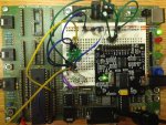
A picture of my setup is attached. I have removed the aux resistor/capacitor filter to reduce clutter as it has not proved to affect anything and the picture was made during testing with 360R pull-ups.
Is there a further way to debug this?
Thank you for your time,
Edmunds
Back with some research and some results.
Tried another picaxe chip. Exactly the same result. The readfirmware command returns decimal 179. Is that good or bad?
Tried another 3D magnetic sensor chip. Exactly the same result.
With that out of the way, I scoped SCL and SDA for voltage. Low is about 0.8V and is hardly affected by the value of the pull-up resistors (within reasonable values of 330R to 15k). 0.8V is probably fine, as it is the same for the bit-banged code that does work.
A picture of my setup is attached. I have removed the aux resistor/capacitor filter to reduce clutter as it has not proved to affect anything and the picture was made during testing with 360R pull-ups.
Is there a further way to debug this?
Thank you for your time,
Edmunds
Last edited:
I can't think of anything other than comparing the logic trace with bit-banging which works with that for HI2C which doesn't. You could try slowing down the HI2C by fiddling with the I2CSLOW value to see what effect that has.Is there a further way to debug this?
I am not sure what debugging will achieve though. If it doesn't work it doesn't work. Knowing why won't necessarily be a help though I can understand the curiosity in wanting to know why it doesn't work and a desire to have it work.
It might be better to move on to the other I2C device you say also doesn't work. If there is some systemic issue then that might help reveal what it is.
Hippy, thank you for your reply. This thread describes the battle with the device in question: http://www.picaxeforum.co.uk/showthread.php?29745-BNO055-failureIt might be better to move on to the other I2C device you say also doesn't work. If there is some systemic issue then that might help reveal what it is.
I got it to work somewhat via UART, but this is not what I wanted and what I can use practically. I have bought an expansion board for the device to eliminate hardware issues, but have not had time to attend it. However, the similarity of the problem as far as I remember it is that it did run at slow processor speeds and did not run with higher clock rates. It also got stalled after running happily for a while and how fast it would stall was related to higher clock rates. Now an obvious thing to try with that knowledge, would be to try and run hi2cin/out at, say, m2 processor speed for 3D magnetic sensor just to see if that helps. I did not try to bit-bang for that device back then, but could try that, too at some point.
/Edmunds