In my previous post I needed 1 more input using the 08m pic. After investigating I could use input 1 and then switch my output to Output 0. I guess I am not sure if that is acceptable. I understand that a disconnect command is required to disable the communication after download is that needed to use out 0 which is also serout?
Found the option out 0
- Thread starter Lamtron
- Start date
lbenson
Senior Member
You can safely use output 0 without a disconnect. If you are going to program your chip "in-circuit", you need to make sure that what you have connected to pin 0 won't interfere with a download (typically, it won't), and that downloading won't damage what you have connected.
If you are worried, you can add a 3-pin header with jumper--jumped one way for download, the other way for normal operation.
If you are worried, you can add a 3-pin header with jumper--jumped one way for download, the other way for normal operation.
procfanousek
Member
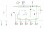
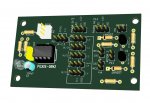
As Ibenson said, 3-pin header with jumper is very useful for this. I attached two pictures where you can see how I do it. It is plug marked JP-C.0. If put left - programming, right - operation. I use this solution on all my boards.
Attachments
-
 233.5 KB Views: 63
 -
 107.5 KB Views: 60
Thanks for your helpAs Ibenson said, 3-pin header with jumper is very useful for this. I attached two pictures where you can see how I do it. It is plug marked JP-C.0. If put left - programming, right - operation. I use this solution on all my boards.
Hello from NYAs Ibenson said, 3-pin header with jumper is very useful for this. I attached two pictures where you can see how I do it. It is plug marked JP-C.0. If put left - programming, right - operation. I use this solution on all my boards.
After looking at your schematic and pcb layout I was wondering what software package are you using for schematic capture and pcb layout?
westaust55
Moderator
From this thread I suggest KiCAD is being used by Procfanousek:
http://www.picaxeforum.co.uk/showthread.php?29881-kiCad-libraries-for-picaxe&p=309751#post309751
http://www.picaxeforum.co.uk/showthread.php?29881-kiCad-libraries-for-picaxe&p=309751#post309751
procfanousek
Member
Yes, it is KiCAD.From this thread I suggest KiCAD is being used by Procfanousek:
http://www.picaxeforum.co.uk/showthread.php?29881-kiCad-libraries-for-picaxe&p=309751#post309751