Hi All,
I have an 8 LED flasher circuit using 8 outputs of a Picaxe 20X2. It uses the standard LED interface circuit, and simple 'LED is on when Picaxe output is high, and off when output is low' type stuff. The circuit works very nicely after advice I obtained from here, but I want to update it. (There are various other things going on with the circuit, but I've simplified it to only the LED interfacing to ask my question).
I want to make the 8 single LEDs into 8 pre-made LED light strings - so the Picaxe is turning on and off 8 LED light strings in a light show - rather than 8 single LEDs. I'm talking about the copper wire micro LED type strings like these.
My light circuit was like the one below. (I've 'hidden' everything but the light interfacing circuits to make things clearer - imagine the Picaxe is powered by the standard minimum operating circuit.)
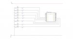
That was working nicely for eight LEDs, but I realise from reading other people's threads and my own threads on here that the Picaxe will not be able to provide current for all those LED strings at once. I need some kind of external driver. My project needs to fit inside a very tight space. Every component counts. From researching solutions on here - a Darlington Array looked like the best option for tight space. (Please correct me if there is a more elegant, less current-hungry solution available for my application.)
In all the great advice I found on here about this - I just could not find a circuit diagram with LEDs to show me how to add a Darlington Array into the mix for powering LEDs. I found this diagram - but it doesn't go so far as showing how the LEDs should be wired. I only had verbal descriptions for lots of applications to go by - so forgive me if I am utterly off with how I'm trying to wire this. I know a darlington only sinks current - and cannot source it from my reading - so I tried wiring one of my 8 LEDs to be powered by the Darlington as an initial, tentative test. If it worked, I'd make all 8 follow suit.
Unfortunately, my test was unsuccessful. I hope you can help me with what I'm doing wrong.
Test #1:The 8th LED should be being powered by the Darlington Array. This is the circuit I tried after trying to piece together written descriptions and the Circuit Creator diagram (Again, I've 'hidden' everything but the light interfacing circuits to make things clearer - imagine the Picaxe is powered by the standard minimum operating circuit.):
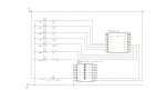
First problem: Now, the LED does flicker. However - it is 'dim' when it should be ON (about half brightness), and bright when it should be OFF. I need to solve this - and make it turn off, and on again.
Second problem: After more reading on this forum - it looks like I should expect a Darlington to flip the result of the Picaxe's output (On when the output is Low, off when the output is high), but my LED isn't going on and off at all - its going dim and bright! Not sure why that is... If I need to flip the logic of my program for the LED patterns - is there any easy way I can flip the logic for certain outputs in my Picaxe program - or do I just have to go through manually and swap every 0 and 1 for my LED sequences?
Other Solutions? Whether I can solve those two problems or not - please also let me know if I am going about replacing single LEDs with LED strings in the right way. I'm willing to switch to any better or more elegant solutions - but they need to be easy enough to understand for a beginner dabbler like me - and require as few components as possible, and have as small components as possible. If I can make battery life longer in any way - GREAT! But I need it to fit inside a very small package that already has a lot of components.
My dream solution would be something in the same format as a ULN2803A, but something that could source the current and voltage from the power source instead of the Picaxe in order to protect the Picaxe. Something that makes the LEDs on when the Picaxe output is High, and Off when it is low, so the program doesn't have to be flipped upside down. But I assume a chip like that doesn't exist - because everyone would be suggesting that instead of Darlington Arrays, and MOSFETs etc. (I'm not talking about a TBD62783A, am I?)
As you can tell, I'm a bit confused. Mainly because I don't have any clear schematics for any of the solutions that tell me how to wire these things for my type of application. If anyone can point me towards a good solution for my problem, and a simple schematic for how to wire it - I'd be most grateful.
I have an 8 LED flasher circuit using 8 outputs of a Picaxe 20X2. It uses the standard LED interface circuit, and simple 'LED is on when Picaxe output is high, and off when output is low' type stuff. The circuit works very nicely after advice I obtained from here, but I want to update it. (There are various other things going on with the circuit, but I've simplified it to only the LED interfacing to ask my question).
I want to make the 8 single LEDs into 8 pre-made LED light strings - so the Picaxe is turning on and off 8 LED light strings in a light show - rather than 8 single LEDs. I'm talking about the copper wire micro LED type strings like these.
My light circuit was like the one below. (I've 'hidden' everything but the light interfacing circuits to make things clearer - imagine the Picaxe is powered by the standard minimum operating circuit.)
That was working nicely for eight LEDs, but I realise from reading other people's threads and my own threads on here that the Picaxe will not be able to provide current for all those LED strings at once. I need some kind of external driver. My project needs to fit inside a very tight space. Every component counts. From researching solutions on here - a Darlington Array looked like the best option for tight space. (Please correct me if there is a more elegant, less current-hungry solution available for my application.)
In all the great advice I found on here about this - I just could not find a circuit diagram with LEDs to show me how to add a Darlington Array into the mix for powering LEDs. I found this diagram - but it doesn't go so far as showing how the LEDs should be wired. I only had verbal descriptions for lots of applications to go by - so forgive me if I am utterly off with how I'm trying to wire this. I know a darlington only sinks current - and cannot source it from my reading - so I tried wiring one of my 8 LEDs to be powered by the Darlington as an initial, tentative test. If it worked, I'd make all 8 follow suit.
Unfortunately, my test was unsuccessful. I hope you can help me with what I'm doing wrong.
Test #1:The 8th LED should be being powered by the Darlington Array. This is the circuit I tried after trying to piece together written descriptions and the Circuit Creator diagram (Again, I've 'hidden' everything but the light interfacing circuits to make things clearer - imagine the Picaxe is powered by the standard minimum operating circuit.):
First problem: Now, the LED does flicker. However - it is 'dim' when it should be ON (about half brightness), and bright when it should be OFF. I need to solve this - and make it turn off, and on again.
Second problem: After more reading on this forum - it looks like I should expect a Darlington to flip the result of the Picaxe's output (On when the output is Low, off when the output is high), but my LED isn't going on and off at all - its going dim and bright! Not sure why that is... If I need to flip the logic of my program for the LED patterns - is there any easy way I can flip the logic for certain outputs in my Picaxe program - or do I just have to go through manually and swap every 0 and 1 for my LED sequences?
Other Solutions? Whether I can solve those two problems or not - please also let me know if I am going about replacing single LEDs with LED strings in the right way. I'm willing to switch to any better or more elegant solutions - but they need to be easy enough to understand for a beginner dabbler like me - and require as few components as possible, and have as small components as possible. If I can make battery life longer in any way - GREAT! But I need it to fit inside a very small package that already has a lot of components.
My dream solution would be something in the same format as a ULN2803A, but something that could source the current and voltage from the power source instead of the Picaxe in order to protect the Picaxe. Something that makes the LEDs on when the Picaxe output is High, and Off when it is low, so the program doesn't have to be flipped upside down. But I assume a chip like that doesn't exist - because everyone would be suggesting that instead of Darlington Arrays, and MOSFETs etc. (I'm not talking about a TBD62783A, am I?)
As you can tell, I'm a bit confused. Mainly because I don't have any clear schematics for any of the solutions that tell me how to wire these things for my type of application. If anyone can point me towards a good solution for my problem, and a simple schematic for how to wire it - I'd be most grateful.
