LCD Keypad Shield

marks

Senior Member
Can be found for less than $5 which seems like good value.
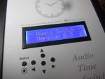
the unique thing it has 6 key switches to get your project up and running quickly.
there seem to be a lot of different makes but all seem to work identically.

Unlike older LCD's these new 1's work happily at 4v you just need to adjust the contrast to suit.
when you power up you will also find the backlight led will be at full brightness.
If you want to reduce this send a low signal to D.10 the transistors base which controls it.
If your using the RST switch it needs to have a pullup resistor.

The code example shows the pinouts and how we can connect to a 20m2
- dim the backlight using hpwm
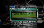
-display keyvalues on the LCD from O to 6 depending on the key pressed
if you press multiple keys the lower valued or reset takes priority.
Code:
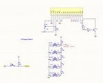
'#Picaxe 20m2         .------------------------.
'                     | LCD KeypadShield       |
 SETFREQ M32       '  |         _ _ _ _   Aref |
'                     |        |       |  GND  |
 dirsB = %00001111 '  |        |       |  D.13 |    B.7  Hi2C SCL
 dirsC = %10111111 '  |        |       |  D.12 |    B.5  Hi2C SDA
'    %-------- C.6 -->|  RST   |       |  D.11 |
'(requires pullup)    |  3V3   |    16 |  D.10 |<-- C.4  SwitchLED(optional)
'    RST Sw 5      -->|  5V    | 2   6 |  D.9  |<-- C.3  Enable
'                  -->|  GND   | 1   4 |  D.8  |<-- C.2  RS
'                     |  GND   |       |       |
'                     |  VIN   |       |       |
'                     |        |VDD 15 |       |
'                     |        |    14 |  D.7  |<-- B.3  DB7
'                     |        |    13 |  D.6  |<-- B.2  DB6
'   %-%-%-%-%- C.7 -->|  A.0   |    12 |  D.5  |<-- B.1  DB5	
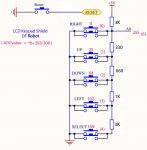
'  SELEC Sw 4         |  A.1   |    11 |  D.4  |<-- B.0  DB4
'   LEFT Sw 3         |  A.2   |       |  D.3  |
'   DOWN Sw 2         |  A.3   |_ _ _ _|  D.2  |
'    UP  Sw 1         |  A.4         TX / D.1  | 
'  RIGHT Sw 0         |  A.5         RX / D.0  |
'                     |___               ______|
'                         \_____________/       
     
 	SYMBOL RS        = C.2
	SYMBOL E         = C.3
	SYMBOL RSTswitch = pinC.6
	SYMBOL Switches  = C.7	
 	SYMBOL senddata   = b0  		
 	SYMBOL index      = b1
	SYMBOL pushbutton = b2
 	
	TABLE   0, ($33,$32,$28,$0C,$01,$02,$06)  '(4Bit)(2line/5x8)(Display On)(Clear Display)(Return Home)(Entry Mode Set)
IntialiseDisplay:
                 hpwm 0,0,%0010,240,120         ' mode,polarity,B,period,duty (diM lcd LED C.4) @5v duty 000 16ma / 120 21ma / 35ma not connected
       FOR  index = 0 to 6                      ' total current includes 20m2 (about5ma)        @4v duty 000 12ma / 120 16ma / 23ma not connected
 READTABLE index, senddata : pinsB = senddata /16 : PULSOUT E,1 : pinsB = senddata : PULSOUT E,1' Initialise LCD/OLED
  	NEXT index  :  PAUSE 10		
Menu: 
 ReadADC Switches,pushbutton : pushbutton = pushbutton  *6 + 293 /300        'check pushbutton status 0 to 4
  IF RSTswitch = 0 THEN : pushbutton = 5 : ENDIF                             'check reset 5 overide
                                                                             'value 6 no button pressed 
	pushbutton = pushbutton + "0"                                          'convert to ASCII for display										     
Display:
            LOW  RS                                     ' commandmode 
            senddata = 128 : pinsB = senddata /16 : PULSOUT E,1 : pinsB = senddata : PULSOUT E,1' (128-147) Line 1 Cursor Position

           HIGH RS                                      ' charactermode
           FOR  index = 0 TO 14
 	          LOOKUP index,("20M2 KEYvalue ",pushbutton) ,senddata 
 	                       pinsB = senddata /16 : PULSOUT E,1 : pinsB = senddata : PULSOUT E,1' sending characters  
           NEXT index
     goto menu
 

Attachments

Last edited:

inglewoodpete

Senior Member
The Shield LCD looks very similar to the Deal Extreme one that I documented back in 2012. At least they have corrected the silk screen spelling in this version!

A couple of hardware mods that are worth considering for this board are:
  1. Carefully unsolder and remove the contrast pot and resolder it on the rear side of the board. This allows the board to be mounted on a panel or your enclosure.
  2. The membrane switches can be replaced with ones with a 12mm actuator. As above, this allows you to mount the LCD on a front panel and have the buttons protrude through the panel.
Refer to the picture (I also removed the reset switch completely).

Timer Panel LoRes.JPG
 

marks

Senior Member
I might go looking for a few different types of shields but are never too keen when a datasheet is not made available.
I started the thread to help with the pinouts and some imformation and light code to get started!
I did assume all these lcd keypad shields were identical but this appears not to be the case.
the lcd side seem to follow the same pinouts, but there are quite a few different ladder switch resistor arrangements.
So it would be a good idea to check your own adc switch values.
For those that wish to make there own version2 seems a good design see the attachment.
and for the DF robot shields that are new will add an attachment to post 1 for the switch resistor arrangements.
I think for a lot of shields in use using a 20m2 probaly makes more sense,you can make reuse of the reset sw,
there are also ones arround already with the longer switches.
 

Attachments

GY44

New Member
Hello marks,
could you please explain the maths in pushbutton = pushbutton *6+293/300
was this derived from imperical data ?
regards,
gy44
 

marks

Senior Member
Hi GY44,
Welcome to the forum
I received two lcd shields from different sources one green backlit and one blue backlit
just a couple of weeks before my first post #1. which i also added the diagram.
both marked DF Robot (LCD Keypad Shield) both work identically.
the resistor values were discovered using a Fluke Meter and found to be
3k pullup with resistor ladder values of +330 +660 +1000 +3000 ohms.

I prefer to use 8bit ADC for this ,using the lower resolution also acts as a filter.
@ 8bit will return values of (255,0,25,64,102,159)tested using a 20m2
there seems to be an attempt at spacing there
multiply up until we get some distingtive numbers
times 6 gives 150 , 384 , 612 , 954 divide 100
or 1,3,6,9 divide by 3 becomes 0,1,2,3
then add an offset +1 it becomes 1,2,3,4
simplifying this becomes b0=b0*6 /300 +1
because theres a bit of switch resistant and maybe some noise also may cause the value to step up
so for our zero value we also except 1 (although this didnt seem to be required)
so then becomes b0=b0*6 +293 /300 we can even further simplify this to b0=b0+48/50

Although this works well.
Maybe the original designer did try to improve on this
and there seems to be no circuit that matches this on the web
(I'm starting to think this is an old design sold cheap on ebay lol)
if you go to the DF Robot web page shows a different design using a lower pullup
and values more central to there steps(perhaps an attemp to combat noise)
2k pullup with resistor ladder values of +330 +620 +1000 +3300 (this seems to be more common)
@ 8bit will return values of (255,0,36,82,126,185)
the original code i wrote should work fine with these values as well !

Putting more thought into a design can always make it easier to code and more efficient.
less affected by noise and resistor tolerance(but these days smd components seem to be far more accurate ,even regulators are spot on.)
heres an example I pencilled out
using a 3.9k pullup with ladder values of +240 +180 +200 +200 +240 +270 +330 +270
@ 8bit should return values of (255,0,14,24,34,44,54,64,75,84)
code becomes b0=b0/10 equals (25 ,0,1 ,2 ,3 ,4 ,5 ,6 ,7 ,8)and easy to expand upto 24
 
Last edited:
Top