PhilHornby
Senior Member
In the next phase of my project, I want to trigger two Triacs to control two 1KW heater elements. The elements are physically inter-connected and the centre point is currently used as the Neutral. The elements will be switched on either together, or separately for several minutes at a time.
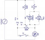
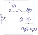
I've never fully understood Triacs, and there seem to be different ways to connect them to the load. The following diagram shows the methods that seem the most common :-
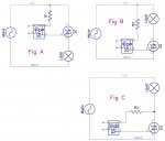
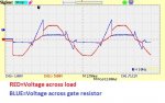
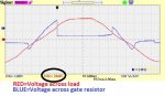
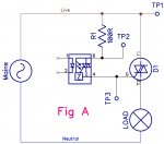
Given that I have two Triacs, and two loads connected via their Neutrals, "Fig A" would seem to be the natural choice of configuration. However, since the opto-isolator will be triggered continuously for several minutes at a time, I am worried about the wattage rating of the resistor. (I can see that in "Fig C", when the Triac conducts it takes away the current flowing in the resistor - but I don't fully understand what happens in "Fig A" and "Fig B".)
If necessary, I can rewire the heaters so their common point is Live, rather than Neutral, but I'd prefer not to.
I've never fully understood Triacs, and there seem to be different ways to connect them to the load. The following diagram shows the methods that seem the most common :-
Given that I have two Triacs, and two loads connected via their Neutrals, "Fig A" would seem to be the natural choice of configuration. However, since the opto-isolator will be triggered continuously for several minutes at a time, I am worried about the wattage rating of the resistor. (I can see that in "Fig C", when the Triac conducts it takes away the current flowing in the resistor - but I don't fully understand what happens in "Fig A" and "Fig B".)
If necessary, I can rewire the heaters so their common point is Live, rather than Neutral, but I'd prefer not to.
")