techElder
Well-known member
Geez. That's not even electronic. Something akin to an oxcart pulled by a Japanese robot.a pair of relays switched by the PicAxe
Geez. That's not even electronic. Something akin to an oxcart pulled by a Japanese robot.a pair of relays switched by the PicAxe
Well I had assumed you would be selecting either 1/4 heat, 1/2 heat, 3/4 heat or full heat for some continous period of time, not attempting to vary the power to maintain a target temperature. If that is the object of the exercise how about rectifying the AC for the heating elements then use Triacs to PWM the resultant DC?Very droll
They're going to 'click' aren't they? ... at random intervals")
I've seen similar effects when testing the motor drivers at College. I was always told by the *clever people* that this was down to the motor momentarily becoming a generator. As they had the degrees, I had to believe their words.Any views on that current flow graph?
I thought PicAxe were British?Geez. That's not even electronic. Something akin to an oxcart pulled by a Japanese robot.
That might be the "correct" way to avoid interference and "flickering" of other lights. But not by using a Triac or SCR/Thyristor because AFAIK they only switch off at the current-reversal of an ac source. From my (relative) youth I remember "gate turn-off" SCRs, but I believe they needed very large reverse gate currents and were little-used. You could use a FET of course, probably with PWM at quite a high frequency to make the filtering easier. But it's still basically a 2 kW (or more) dc power supply, so the mains reservoir capacitor would need to be thousands of uF at 400 volts (with probably a large inductor to smooth the current as well).how about rectifying the AC for the heating elements then use Triacs to PWM the resultant DC?
I suppose that will be the best/simplest/easiest case - I'll have to do some experiments (in Winter!) to see if it's possible. The other (convector) heaters in the cottage use 0.3125°C hysteresis, achieved by simple ON/OFF control and I'd like to match that. (0.3125°C is 5/16 in DS18B20 terms. Dimplex claim 0.3°C for their latest heaters, so I'd thought I see if I could do the same)Well I had assumed you would be selecting either 1/4 heat, 1/2 heat, 3/4 heat or full heat for some continous period of time, not attempting to vary the power to maintain a target temperature.
I thought this was a great answer - for a couple of hours - until I remembered that this effect is not measurable with the fan only ... it seems related to the heater elements, somehowHe also said:I've seen similar effects when testing the motor drivers at College. I was always told by the *clever people* that this was down to the motor momentarily becoming a generator.
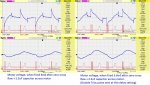
The graph comes from the output of a 'sensing' coil from a commercial Energy Meter. I only put it in circuit to confirm that the Picaxe/SSR combination were indeed turning on and off for 60mS as designed. Likewise, the 'Sangamo Weston' clamp meter was only there to give a rough indication of current flow - I didn't expect any great accuracy, but it does seem to be of the right order of magnitude. There's no measurable output from either of these devices, when only the fan is in operation.Is your current waveform measured with the "clamp" meter or a series resistor? It appears to have an ac-coupled "step" with a time constant around 10ms; the positive step at the start of the power burst, up to approximately the level of the "T" marker (probably just a coincidence), then the negative step where the burst terminates. That might be an artifact of the clamp meter circuit or perhaps a thermal effect.
13% was higher than I'd been expecting ... but that's what I measuredhe also said:13% slip sounds rather high, but it might be caused by the motor cage having a rather high resistance (by design or economy). As was said above the "load" (or amount of air moved) with a fan is proportional to the cube of its rotational speed, so you might not need a large rpm variation. Therefore a simple impedance in series with the motor could be all that's needed. The load (drag) will be so little at lower speeds that there's probably no risk of the motor stalling.
. That particular fan heater (the supermarket one) has two large 'lobes' that make up the fan; maybe the fan is oversized for the motor?Yes that's the plan.Might not be an issue though so long as one and only one is on at the same time.
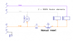
It turns out that the thermostats/cut-outs are, in fact, in the common return for both elements. One is rated at 90°C and is what I thought it was ... the other is rated at 125°C and is a Manual Reset type, that I've not seen before.My guess is that currently, the air temperature never exceeds 80 °C - it seems to use the type of thermostat commonly found in gas boilers ... though the wiring seems a little odd. (The heater has two separate elements and there are two of these thermostats to act as overload cut-outs. However, they're wired in series with just one element, as far as I can tell...)
See: https://www.dropbox.com/s/o62hrsfyn2ip9c5/20170719_211325.jpg
and some more photos of the innards, for those who are interested...
https://www.dropbox.com/s/4nxokmszzoy6aqr/20170719_211404.jpg
https://www.dropbox.com/s/miv16tffhbmm1o1/20170719_214504.jpg
Searching around the web, I've found a few references to this phenomenon, when switching large inductive loads. I've been thinking of the heater elements as resistive loads; but given that they're physically formed as coils, they're probably quite inductive as well!Observing the current flow to the heater, in the Picaxe+Heat configurations shows an odd effect :-
View attachment 21413
- Why does current continue to flow when the SSR has been turned OFF?
- Why is the amplitude of the first half-cycle after SSR triggering, lower than the following five?
Presumably, the substantial amount of current flowing after SSR turn off, is related to the burst firing of the heating elements; on Fan only I can't detect any measurable current at all, using this method.
I'm not convinced that feedback and incremental control of a heater fan is necessary.
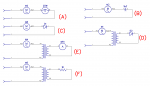
I decided to try some of the simpler, 'analogue' methods of fan speed control. I used the following circuits (with the cheap 'supermarket' fan heater) :-In theory, this would only reduce the voltage applied to the motor, this may affect the speed, but the theory would suggest not.
 (Click to view!)
I remembered I have a multimeter that performs inductance measurements. The heater elements have no inductance that I can measure. Furthermore, applying a simple Power=V2/R calculation gives the expected answer; revealing that there's no Reactance involved. So much for that theory!I've been thinking of the heater elements as resistive loads; but given that they're physically formed as coils, they're probably quite inductive as well!
I did some measurements of my two fan heater motors (and did some calculations, with the help of this web page) :-Me as well said:
- "B" - 2µF capacitor. This had no discernible affect on the motor speed. Unfortunately, the only other mains-rated capacitor combination I could come up with, was only about 0.07µF; the fan didn't operate with those in series and I have no other suitable capacitors, in my 'bits box' :-(
It can't be inductive coupling, because removing power to the heater would have an immediate effect - and it doesn't. The fan speed does slowly come back down, but not as quickly as it rises when the heater is turned on. Other than as a general effect, there's no real correlation between the temperature of the air coming out and the speed of the motor.The measured fan-speed is interesting though - because it's definitely not constant. When I first powered it on, it (visibly) accelerated to 1260rpm (full speed is 3000rpm for this motor). When I switched on the heater element
[*], the fan speeded up?!? ... eventually reaching about 1900rpm. Removing the heat, made it slow down to about 1600rpm.
[*] Could this be some sort of inductive coupling effect, between the heater element and my transformer? ... or the hotter, less dense air posing less of a load for the fan
I dismantled the 'current sensing' module I was using and found it was fitted with a 220Ω shunt resistor. I changed this for 2.2K and now I can see the same odd current graph, using only the fan motor. I'm pretty certain this is the TRIAC being held on by the out of phase current in the motor. Presumably what I was seeing originally, was the inductance of the motor holding the TRIAC on, which then allowed the heater elements to continue drawing current as well.Searching around the web, I've found a few references to this phenomenon, when switching large inductive loads.
It occurred to me, that what I had actually created was a Series R-L-C circuit... with a resonant frequency of approximately 49Hz! On that basis, there's presumably no wonder it hadn't the slightest impact on the motor speed!I also said:The Dimplex motor has a DC resistance of 220Ω and an inductance of 4.8H. 4.8H equates to 1508Ω @ 50Hz, so the combined Impedance works out at 1523Ω. The reactance of a 2µF cap. is approx. 1600Ω - so I would have expected that to be about the right value to half the speed of the motor - I wonder why it didn't? (I checked the cap. ... my meter said 2.2µF).
 Across the capacitor!
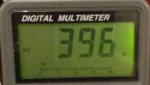 Across the motor!
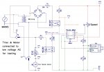
#picaxe 08m2
;
;Interrupt On Change SFRs
;
Symbol IOCAP            = $F1                   ;$391 - Capture positive edges
Symbol IOCAN            = $F2                   ;$392 - Capture negative edges
Symbol IOCAF            = $F3                   ;$393 - Capture flag
;
; Symbols
;
symbol MOC3021          = C.1
;
; Variables
;
symbol EventCapture     = b20
;
; Start Program
;
      setfreq M32                               ;need-for-speed...
      ;
      ; Our Zero-cross detect pulses are high going and arrive on PinC.2 (Schmitt Trigger input)
      ;
      PokeSfr IOCAP,%00000100                   ;capture positive-going transitions on C.2
      do
            PokeSFR IOCAF,0                     ;reset capture event - wait for next zero-cross event
            ;
            ; Wait for zero-cross event
            ;
            do
                  PeekSfr IOCAF, EventCapture   ;get pin no.s that have edge detections (s/be none, or C.2)
            loop while EventCapture = 0
            ;
            ; Assume it was C.2 that was detected = ZERO-CROSSING detect
            ;
            Pause 40                            ;wait 5mS - 1/2 cycle
            Pulsout MOC3021,200                 ;Send 250uS pulse to optocoupler, to trigger TRIAC
loop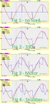 .
.I calculated (ok - I cheated and used Excel's "Goal Seek"It occurred to me, that what I had actually created was a Series R-L-C circuit...
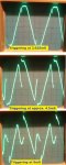
UPDATED: It struck me, that a 2.2uF capacitor in series with the motor, was going to produce some serious voltages. I repeated the experiment and took some measurements...
Looking on the bright side, there's enough information there to calculate a better value for the motor's inductance...
) the value of L (motor inductance) as 6.5H. This is substantially higher than the value I'd measured with my meter ... and confused me somewhat...It turns out there is more to this than meets the eye...For the initial tests, the motor is being fed 18VAC @ 50Hz. The motor is therefore (obviously) not spinning - but this doesn't seem to upset it (or the measurements I've made so far). I tried spinning the motor using a hair-dryer and was somewhat surprised that it does not function as a generator. Various googlings lead me to believe that this is normal, unless it reaches its theoretical synchronised speed of 1500rpm).
) - and didn't cure the actual problem.I've only calculated inductance a few times, but I don't remember entering any factors for "speed."I connected the motor to my meter and measured the inductance again - 4.8H or thereabouts. I then applied the hair dryer to the fan, and spun it up to some reasonable rpm and re-measured. The inductance now read 6.2H or thereabouts. I've not seen that effect documented anywhere and I hereby claim my nobel prize. This explained why the timings had changed - the motor's inductance varies with speed.
 )
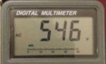
)I've reconfigured the circuit for low voltage (18Vac) operation, and tried a 2.2uF capacitor across the motor (The 1.5uF cap. is still in the post). I recorded the voltage across both the Triac and the motor, at the extremes of operation (timing wise)....I'm going to try one last experiment and add a 1.5uF capacitor across the motor. This should prevent the 'reactive' current flowing through the Triac ...but will it do anything to help it turn off when it should. (Or will I generate some huge voltage and destroy it?
 (The small red 'blips' are the zero-crossing pulses; the taller ones - where present - are the Triac firing pulses. They are pre-recorded references signals, and may be slightly out of register!)
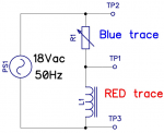 I adjusted the preset until the voltage across the TP1/TP2 was the same as that across TP1/TP3 (ignoring the motor's own internal resistance)
 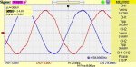 Mysteriously, these signals are 7.2mS apart ... which is not what I expected. Could there possibly be some other component contained in the motor housing, that's affecting the measurement?
Entirely possible. Worth noting that the largest signal I have produced from the motor, using the hairdryer as propulsion is only 24mV though. Also worth noting, that measuring inductance using the method above does not vary if the motor is spun.You probably have discovered more truths about your meter than your inductor! I'd guess that there is some residual magnetism involved with generating a volt or two while the fan is spinning.
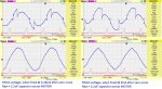
Well the capacitor across the motor didn't have a positive effect: the "1.5uF" cap. I ordered, actually measured 1.3uF - so I ordered another one. That measured 1.3uF tooWhen the 1.5uF cap. arrives, I'll set it back to mains operation and record the results. Perhaps these nice smooth waveforms will mean I can achieve a greater range of speeds...
(could be my meter, but the 2.2uF cap. I already had measures 2.2uF...))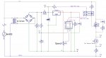
#picaxe 08m2
;
; Symbols
;
symbol Speed            = C.1                   ;Pot. across supply, used to control fan speed
symbol ZCD              = PinC.2                ;connection to bridge rectifier - limited to 3.9V by zener
symbol MOC3021          = C.4                   ;low-going connection to MOC3021 opto-triac. High is other side
                                                ;of 5V regulator. The Pic can sink more current than it can
                                                ;source, and this also reduces the load on the regulator

symbol MinDelay         = 35                    ;35 gives 3.72mS after zero cross.
                                                ;Since theoretical 35/8 = 4.375mS, Zero cross must be detected
                                                ;655uS prematurely

symbol MaxDelay         = 54                    ;54 gives 6.2mS (about 100~200rpm - not particularly stable)
;
; Variables
;
symbol CurrentPause     = b20                   ;Delay between ZCD and Triac firing (currently in use)
symbol PauseTime        = b21                   ;Delay between ZCD and Triac firing (desired)
symbol ADC              = b22                   ;reading (0-255) from Speed Pot.
symbol lastADC          = b23                   ;previous reading to detect change.
symbol SavedTime        = W12                   ;last time loop executed (to determine if time to do ADC)
      #macro FireTriac

      do : loop while ZCD <> 0            ;faster than using an interrupt...
                                                ;This happens when signal drops to 1V approx.
            Pause CurrentPause                  ;wait for time required.
            Pulsout MOC3021,400                 ;Send 500uS pulse to optocoupler, to trigger TRIAC
      #endmacro

      ;
      ; **** START PROGRAM ****
      ;

      setfreq M32                               ;Haven't tried lower clock speeds - this is a real-time program ;-)
      pause 16000                               ;wait for terminal
      sertxd (cr,lf,"Fan Speed Demonstrator")
      high MOC3021                              ;we want a low-going pulse, so set port HIGH

      ;
      ; Bring motor up to full speed initiallly. It doesn't like being STARTED on a low power setting.
      ;
      ADC=0 : gosub CalculateDelay              ;set parameter(s) for full power
      CurrentPause = PauseTime                  ;say we've been using these parameters up to now.

      sertxd(cr,lf," -- accelerating motor to full speed --")
      do
            FireTriac                           ;wait for Main zero-cross and trigger Triac
      loop while TIME < 8                       ;about 2 Secs @ 32Mhz?
      ;
      ; Get first ADC reading from SPEED pot.
      ;
      readadc Speed,ADC                         ;get power setting
      gosub CalculateDelay                      ;convert to Delay in mS
      lastADC = ADC                             ;say it's same as last reading
      Time = 0: SavedTime = 0                   ;turn back time
      sertxd(cr,lf," -- entering normal program loop --")
      ;
      ; *** MAIN LOOP ***
      ;
      do
            ;
            ; Smoothly accelerate or decelerate to chosen speed - by increasing or decreasing
            ; the delay setting by one, until it matches the target.
            ; This only takes a maximum of 20 cycles - less than 500mS, but gets rid of the
            ; "thumps" and "bumps" from the motor, that can occur otherwise.
            ;
            if PauseTime > CurrentPause then
                  inc CurrentPause              ;we're below target
            elseif PauseTime < CurrentPause then
                  dec CurrentPause              ;we're above target
            endif
            ;
            ; Fire the TRIAC
            ;
            FireTriac                           ;wait for Main zero-cross and trigger Triac
            ;
            ; Check pot for changed delay setting
            ;
            if TIME <> SavedTime then           ;only check every 500mS or so, not every half-cycle!
                  readadc Speed,ADC             ;get pot. setting
                  if ADC <> lastADC   then      ;only if it has changed...
                        gosub CalculateDelay    ;calculate new delay
                        LastADC = ADC           ;save ADC value, to detect future change
                  endif
                  SavedTime = Time              ;remember when this change detected
            endif
            ;
            ; END LOOP
            ;
      loop
CalculateDelay:
      ;
      ; ADC value has changed. Convert 0-255 into 35-54 (or whatever limits are)
      ;
      b0 = MaxDelay - MinDelay * ADC / 255      ;scale the adc reading
      PauseTime = MinDelay + b0                 ;offset from minimum
      sertxd(cr,lf,"ADC:",#ADC,", Delay:",#PauseTime)

return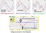 )
)Ah - I see!My comment was triggered by the the fourth chart referencing zero-crossover points.
Almost. You determine a zero by it not being non-zero.I know some of the PIC family have built-in zero-crossing detection facilities and it intrigues me as to how it is achieved. How do you detect 'the absence of a signal'? ... using a very high gain comparator maybe?
do : loop while ZCD <> 0pulsin ZCD,0,W13