Hi everybody,
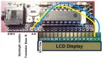
I was wondering why the 16-pin output connector of this Picaxe Board did not conform to the pinout of a standard LCD !? (1-2-3 ... 14-15-16)
It is realized to the standards of some strange OLED-2 Lines (15-16-1-2 ... 12-13-14) and is therefore not adapted to conventional LCD displays.
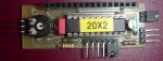
Too bad, especially since this board is designed to place a switching transistor backlight (for LCD display ! ) ... but the pins do not line up!
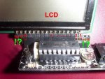
I was wondering why the 16-pin output connector of this Picaxe Board did not conform to the pinout of a standard LCD !? (1-2-3 ... 14-15-16)
It is realized to the standards of some strange OLED-2 Lines (15-16-1-2 ... 12-13-14) and is therefore not adapted to conventional LCD displays.
Too bad, especially since this board is designed to place a switching transistor backlight (for LCD display ! ) ... but the pins do not line up!
") .
.