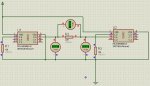
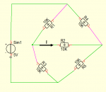
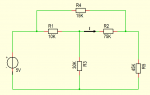
Hi everyone, I have a question regarding a circuit in which I am connecting the output of one Picaxe to the input of another. I understand that it is recommended practice to place a series resistor between the input/output of the two chips in the event that the input accidentally gets configured as an output and goes low, this creating a short to ground. What I am having trouble understanding is that in the attached schematic, why does the resistor between the input/output have 0 voltage drop across it? Wouldn't it drop the 5V output from the Picaxe on the left, thus presenting 0V to the input of the Picaxe on the right? How does the input of the Picaxe on the right still see 5V? Unclear about this. Any explanation would be greatly appreciated. Thanks.
Attachments
-
 116.5 KB Views: 94
")