OT: Help needed identifying chip 4001

Buzby

Senior Member
Hello,

Everybody knows a 4001 is a quad NOR gate, but is there something specific about a 4001PC ?

I can't find any reference to 'PC', just lots of 'B' and 'UB'.

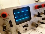
The chip is in the blanking circuit of a vintage miniature CRT scope.4001PC.JPGMS215_intensity_1.PNG

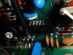
Pins 3 and 4 are both at 0v wrt pin 7, so I think it's broken, but I don't want to remove it till I know what to put in it's place.

Cheers,

Buzby
 

edmunds

Senior Member
It is unlikely anything else than the said NOR gate, package markings may differ from what the IC code is. I.e. it can well be CD4001B, BE or UB and PC can stand for DIP package or something like that. The same way CD is omitted from your part and F 7540 is added. 75 could be production year if the vintage goes back that long :). I was thinking F could mean Fairchild, but could not find anything about package marking on their (very old looking) data sheet for CD4001.

I would take it out and test on a breadboard. With this kind of device should be pretty simple to set it up.


Good luck,

Edmunds
 

fernando_g

Senior Member
Most likely, the "P" means a dual-inline plastic package, and "C" is commercial grade temperature range: 0 to 70C.
 

The bear

Senior Member
@Buzby,
Are you Ok for a spare 4001?
I could drop you one in the post tomorrow, if required.
Would need your address.
Regards, Bear..
 

Buzby

Senior Member
Thanks for the replies, I think they confirm my suspicions, it's just a plain 4001.

This little scope was working last time I used it, about 5 years ago, but it was dead when I tried it today.

Luckily the manual and circuit are well represented online, ( much quicker than searching the loft to find my original 1976 paper copy !. )

If my diagnostic skills are correct, ( I don't like anything over 24v ), pin 3 of the CRT should vary when the 'intensity' pot is twiddled, but it's stuck at -755v.
The heater/cathode is at -743v, and I think that means the beam is being blanked. All the other voltages are within limits, and there is about 11v between pins 7 and 14 of the 4001, so that is being powered OK. It's just that the gates don't seem to be behaving logically.

Tomorrow I shall review my findings, and if nothing changes I shall bite the bullet and chop the IC out. It's in an awkward position, and I don't think there is much chance of desoldering it intact. I don't want to risk damaging the PCB, it's 40 years old !.

I've got a few spare 4001's, mostly of the same vintage as the scope. Thanks for the offer @bear.

This was a cute little scope when it worked. I wanted a Thandar scope when they came out, but couldn't afford one. I rescued this from the bin a few years later. I was well pleased !.

Cheers,

Buzby

Edit : Wired a resistor between pins 1 and 3 of CRT, looks promising !.

MS215_nearly_working.JPG
 
Last edited:

Buzby

Senior Member
Whoopee !.

Removed old 4001, put in a new one, and it's working !.

I wonder if I could hack it ?.

Now that I know vaguely how the blanking circuit works, I could possibly add a Z axis.
( It would just be beam on/off, but that's all I need. )

Time to study the schematic closer.

Cheers,

Buzby
 
Top