Analog question

edmunds

Senior Member
Dear all,

Sorry for a sort of low level question, but analog stuff is really not my cup of tea. Still, it seems.

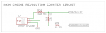
I have a counter set up with an optical sensor that is basically an IR LED and a phototransistor. It is seeing black and white and producing pulses accordingly. The problem is, it has turned out to be a bloody hungry device. It is consuming about 20mA to get the signal up to high level of picaxe working on 2.80V. In my scale, 20mA is a huge tax to pay for this kind of thing. It is probably twice the consumption of 200 components on PCBs, motors and bluetooth module (17mA at full power!) excluding.

Now, I can get it down to sub-mA levels and still get a beautiful square wave on the scope, but this is way too low for picaxe to notice - about 0.6V.

Can I amplify this at lower energy cost than 19mA somehow with as little as possible PCB space taken? Op-amp? Transistor? The frequency is from 15Hz to 330Hz.


Thank you all for your inputs,

Edmunds
 

sghioto

Senior Member
Can you post the schematic of the circuit you are using now? Yes you should be able to get the voltage higher using either an op-amp or transistor.
 

AllyCat

Senior Member
Hi,

In principle it can all be done within the PICaxe, provided that the appropriate dedicated pins are available. With an M2 it needs to be done mainly with SFR commands, but with an X2 there should be more support within the Basic command set.

Basically you need to use one of the on-chip comparators (section 18 in the 28/40M2 base PIC data sheet). Your square wave needs to go to one of the negative input pins (there's usually a choice of 4) and the positive input is internally configured to connect to the "DAC" (section 22 in the PIC data sheet).

The DAC is configured with its output connected to the comparator input but NOT to its dedicated output pin; its Reference internally to Vdd (or the FVR), and the DAC Level set between the square wave's lower and upper levels (these settings are all supported by PICaxe Basic commands).

The only problem is that a single PICaxe pin normally* cannot be used as both an output and input at the same time, so you generally need to make an external pin connection between the Comparator Output and your "Counter" input. *However, the comparator output can be read (and maybe latched) by the software, or can probably set an interrupt with an X2.

But if you don't have a spare comparator/pins, then (if the square wave starts from zero volts) a single NPN transistor with a grounded emitter, 1k (e.g.) from your sensor to the base and 12k from the supply rail to the base should give a full (inverted) square wave on its collector (provided this has a suitable pull-up resistor).

Cheers, Alan.
 

edmunds

Senior Member
Alan, thank you for your input.

I have tried routing comparator output to a pin, but this has the "problem" of it being a serout pin on 40X2. This introduces extra components like a digital switch or a transistor (again) for disabling the input from C.0 and connecting to serial port of the computer (AXEwhatever cable). I need to have the input on C.0 because of settimer count thing, because I think this is the easiest way to handle 'interrupt on every Xth pulse'. Using INTx would work, but I'm kind of short of these pins already and this is more processing to add up the pulses and act only on Xth in software.

So for now, the transistor wins.

Edmunds
 

edmunds

Senior Member
Can you post the schematic of the circuit you are using now? Yes you should be able to get the voltage higher using either an op-amp or transistor.
Yes, sorry for my ignorance, there are existing components that will affect things. They can be changed as needed, of course.

Screen Shot 2017-01-30 at 12.39.52.png


Thank you for your time,

Edmunds
 

fernando_g

Senior Member
The way I've done it, and it works very well, is to pulse the IR LED with a 38 KHz carrier, at very low duty cycles, and then use one of the ubiquitous IR receivers intended for TV and DVD use.

The IR phototransistor can be driven very hard, but with a low duty cycle of less than 10%, which means that the average current is very low.

The IR receiver will decode the 38Khz carrier while highly rejecting other IR sources. When the carrier is detected, a clean digital signal representing the 15 to 300 Hz modulating signal is output to your Picaxe digital port.

Range is excellent and works in a lot of ambient conditions.
 

AllyCat

Senior Member
Hi,

Is that 2.8 volts applied to the 360 Resistor? It doesn't seem consistent with 19 mA. But the "typical" operating current for the LED appears to be around 4 mA, so I'd use about 470 ohms with a 2.8 volts supply, or 680 - 820 from a 3.7 volt LiPo. You might go to an even lower current if there isn't much "ambient" light (inside the vehicle).

The nominal dark (leakage) current through the PhotoTransistor is very low (1 nA @ 25 degC and 20 volts) so you might increase the 33k considerably (thus no need for an additional transistor). The Sharp data sheet (graph) says the (nominal) dark current rises to about 200 nA @ 75 C, but the "worst case" maximum may be up to 100 times larger. However, that's still only 20 uA, or 2v across 100k, which is compatible with a typical PICaxe input threshold of 1.4 volts and a pull-up to 3.7 volts.

IMHO it should be completely "safe" to use up to 150k - 220k pullup, so you shouldn't need any additional amplification at all. Or, my earlier description of a suitable NPN amplifier was rather cryptic, so ask if you need more details.

Cheers, Alan.
 

stan74

Senior Member
If the logic high is > 0.6V try the inputtype command...may be.
Or only turn the led on when you want a reading.
 

edmunds

Senior Member
Or, my earlier description of a suitable NPN amplifier was rather cryptic, so ask if you need more details.
I think I did get it, but will do in case it will still be needed.

I will first check your other suggestions. I'm not sure anymore if 360 was what I have today or what I arrived to to get a good readout on scope. My original design, when I did the calculations and before I started to play with it, require 150R. Maybe 360R was the lowest that still worked for picaxe registering the pin, but still consuming a lot of power. I don't have any 360R 0402 resistors here, so it must be the actual value used is 330R or 470R that I actually have. I think I will now try to do the calibration routine for magnetometer and angle calculation, because these do not require the odometer to work. For the next step, however, the odometer will be needed and it does not work as expected anyway, so I will have to sort it out. I will look at the resistor values and currents again then.

Edmunds
 

fernando_g

Senior Member
Edmunds, please ponder this question for a couple of seconds:
How TV and appliance remote controls achieve very good battery life, while simultaneously achieving over 10 meters range, all with varying ambient light conditions?

It is not by having operate the signal path in linear analog mode.
 

Goeytex

Senior Member
As I read the GP2S60 datasheet the device should operate ok within a range of about 4 - 20 ma LED emitter current, given that the distance from the reflective object is 1/2 mm and that the object has sufficient reflectivity. The datasheet does not go too deeply into the reflection properties of the object but shows "glass" with an aluminium evaporation coating on the back side.

Before adding components to amplify the signal I would first verify that the distance from the object is not more than about 1/2 mm and that the object reflects well. I might try using a glass mirror for testing.
 
Top