CRT Clock

binary1248

Senior Member
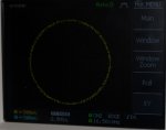
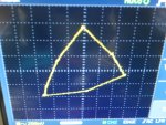
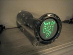
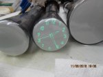
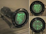
I searched the forums for any thing related to CRT and found nothing. I was wondering if anybody has applied the picaxe to low voltage (les than 1000v) CRT control for a clock, or just drawing things with vector graphics.
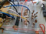
I already ordered a kit to do this using a 2BP1 crt, but it would be fun to try a little circuit control. Lots of stuff on the internet about using micros and the circuits needed to drive the CRT, but before I start breadboarding some kludge circuits, just wondered who else may have approached this using PixAxe chips.
clockcrt001.jpg
Perhaps our good old basic won't be fast enough other than simple squares or pointers.
.
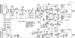
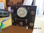
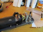
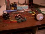
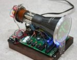
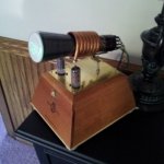
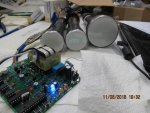
This is the kit I ordered, different CRT (2BP1) Uses a PIC18f26k20 and PIC12f629, also uses external DAC TLC7528 Dual Dac, but comes preprogramed.
.
clockcrt002.jpg
 
Last edited:

Buzby

Senior Member
Hi Binary,

That's a cool kit you've ordered !.

Somewhere in my dark crevices I have all the bits to build a couple of similar clocks. A BP1 CRT, an old Sinclair TV1, umpteen 1980's DACs, but i didn't get a round tuit.

However, I did used to work, in the dim and distant past, for an arcade machine company. There I got intimate with the circuits of machines like Battlezone and Asteroids.

These machines don't work totally digitally. The lines are formed by the discharging of two capacitors, through constant current sources, between the voltages representing the x,y coords of the start and end of the line.

Because the processor only needs to output the voltages representing the ends of the line, and not every voltage inbetween, it should be within the capabilities of a PICAXE to generate a decent display.

If I ever get a round tuit I might have a go myself, but until then I'll just see how you get on !.

Cheers,

Buzby
 

stan74

Senior Member
That looks dangerous! Buzby, "These machines don't work totally digitally. The lines are formed by the discharging of two capacitors, through constant current sources, between the voltages representing the x,y coords of the start and end of the line."
I worked for Electrocoin,who made arcade machines and asteroids used 2 8 pin dacs. I don't know about battle Zone but it did have a separate maths board.
 

Buzby

Senior Member
That looks dangerous! ... between the voltages representing the x,y coords...

I worked for Electrocoin,who made arcade machines and asteroids used 2 8 pin dacs. I don't know about battle Zone but it did have a separate maths board.
Not the full deflection voltages, there were amplifiers after the DACs !.

Yep !. The DACs were followed by a sample-and-hold which held the 'line start' position, then the DAC was set to the 'line end', then the cap charged from one voltage to the other, thus deflecting the line. ( You can get a 'sort of' vector display without the S&H and CC, but all the lines go banana shaped ! )

There was a lot of maths in those games. Not much by modern standards, but still too much for a PICAXE. However, a clock just needs a handful of fixed points, so I'm sure a PICAXE could handle it easily.

Cheers,

Buzby
 

stan74

Senior Member
If you turned the z axis up on those vector monitors you could see the lines connecting the rocks/tanks. The refresh rate was quite low. There's picaxe POV clocks arround. I wouldn't know how to write the code from scratch.
binary, look up octopus tracker..
 

binary1248

Senior Member
Thought my build will be something strange and SciFi looking, something like this one. The vacuum tubes are dummies but I will add LED illumination up thru the glass bottom, maybe flash at one sec intervals with a super bright flash periodically.
I will call it "My Time Machine". Add some miniature analog meters around the base (got lots of those in my junk box) and some non-fuctional mechanical counters (label as future date setting).
clockcrt003.jpg
 

hippy

Technical Support
Staff member
A PICAXE 28X2 at 64MHz can output bytes to both ports B and C and provide a latching pulse every 150us. So could notionally select 130 points on a 256 x 256 grid with a refresh rate of 50Hz.

It seems a PICAXE should be capable of drawing a clock type display on a scope or CRT.

It would probably be best to have a 128 x 256 or 128 x 128 grid so the MSB of one port can be used as a blanking signal rather than use an additional pin on another port which would slow things down.

Separate DAC's would possibly be better than a single dual-DAC otherwise it will require multiple strobes and possibly other control signals, which will slow things down and you'll have the problem of them not changing simultaneously. Though that might not be a problem if only drawing horizontally and vertically lines where only one DAC needs to change at a time. That may actually provide options for some clever optimisation.

But start with what you have and see how that goes.
 

fernando_g

Senior Member
Wow, CRT clocks could as well be the next Nixie Clock retro-fashion.

Definitively a little more complex than a Nixie, though.

Binary, one thing you should be concerned is with CRT burn. I don't know -for instance- if you could periodically switch between Arabic and Roman numerals, for instance.
Also, some sort of auto-dimming the CRT.... I don't know, perhaps a motion sensor which would only turn on the brightness if there was someone on the room actually watching the clock.

Otherwise, withing a year you will have the static numerals solidly etched into the screen.
 

AllyCat

Senior Member
Hi,

Apart from the high voltages, another cause of concern with a CRT vector display is that the spot must never stop moving, even for a few seconds. So you should probably arrange a "watchdog" type blanking circuit that reduces the brightness unless an "I'm running" pulse is continuously delivered by the PICaxe.

And yes, long-term "burning" is a major problem with most phosphor-based "static" displays. The usual solution with CRTs is to continuously move the "image". For a clock, maybe rotate the "12 o'clock" position (of all the digits) by up to +/- 15 degrees, slowly over a period of hours or days. Alternatively, you might modulate the deflection sensitivity a little, by slowly altering the EHT voltage.

Cheers, Alan.
 

binary1248

Senior Member
As I understand it, the image is continuously moved slowly, also I believe it switches to different types of display periodically, such as analog, digital. Good suggestions by all. Thanks. I will keep you updated on this "retro time machine'.
 

tmfkam

Senior Member
The other day I watched this:Oscilloscope music

I was utterly spellbound! All the 'images' are created by music fed into an oscilloscope's X and Y inputs. Jaw droppingly fantastic. I ordered the 'album' and am now looking for an inexpensive CRT based 'scope.

Mind you, I might yet buy one of those clock kits too. They look wonderful.
 
Last edited:

Buzby

Senior Member
Very interesting way of generating the shapes. I saw the same idea in an Elektor article many moons ago. It was a logic display for 16 pin chips, and showed the output on a scope as two rows of 1's and 0's, matching the pinout of a chip. It used a phase shift to generate the 0's, and removed the shift to create 1's.

This clock takes the idea a whole lot further, ( but then again, the Elektor design was all discrete logic, no microprocessor !. )
 

binary1248

Senior Member
Stan74, it isn't for an oscilloscope, it is for this time machine. see opening thread.
.
Or this.
.
clockcrt005.jpg
 
Last edited:

binary1248

Senior Member
IMG_0296.JPGWell, I finished the kit board and it is working (shown). My first time machine will be the old navy o-scope (non-working) and later for my son I will convert the old RCA scope to a clock. For both I will add meters and other stuff to make them strange looking.
The kit uses preprogramed PICS which pin for pin are compatible with the picaxe series. Since I don't have the programs that come with the chips, I hope to replace them with PicAxes just to have some fun to draw shapes, the clock part would be to time consuming.
IMG_0294.JPG
 

binary1248

Senior Member
Here are the two non-working o-scopes I plan to add the crt clocks.
IMG_0293.JPG
To prevent phosphors burn, it moves the image around and also switches between anolg and digital display.
 

Buzby

Senior Member
Cool !.

That's interesting, that you think a PICAXE could be a drop-in replacement.

Does the kit have a circuit diagram included ?.

The clock 'fingers' show as jagged lines, which make me suspect it's not got a real vector display drive.

Still, it's good result.

Cheers,

Buzby
 

stan74

Senior Member
I tried pwm-ing a r-c filter to a x-y scope and drew a square.
Is pixelation from low a-d res? To draw a line/second hand, doesn't it set x and y dacs voltage to centre then change each to the voltage that moves the beam to the end position in a loop and rely on pov. It's analogue.Is it done in small step?? see link below
http://www.msarnoff.org/vectorgen/ Bresenham's line draw algorithm?
I suppose it looks up a table of x-y voltages and send values to the dacs. 120 vals for the hands.
Are you going to try displaying other graphics on a scope?
Interesting stuff, but I hate clocks.
ps Someone mentioned the dac out went to charge caps. the link mentioned fed into linear ramp generators driven by high-speed op amps.
 
Last edited:

binary1248

Senior Member
That's interesting, that you think a PICAXE could be a drop-in replacement.

Does the kit have a circuit diagram included ?.

The clock 'fingers' show as jagged lines, which make me suspect it's not got a real vector display drive.
!) Yes, I believe the picaxe can be a drop-in for the two of the pics on board. On the board are Micrchip 12F629 (similar to 08M2) and 18F26K20 (28 pin slim chip dip).
2) Ckt diagram ? Not yet but I am working on that.
3) Jagged lines certainly indicate a step position, not vector lines.
.
There is a clock out there that uses fragmented Lissajous (sp) patterns to make very clean and smooth patterns of numbers and letters. See picture below..
scope_clock.jpg
 
Last edited:

Buzby

Senior Member
.... Are you going to try displaying other graphics on a scope?
Interesting stuff, but I hate clocks.
Conways Game of Life ?

Noughts and Crosses ? ( On second thoughts, maybe Ones and Crosses )

Reversi ?

BattleZone !

ps Someone mentioned the dac out went to charge caps. the link mentioned fed into linear ramp generators driven by high-speed op amps.
It was me.

Each DAC feeds into a S&H to latch the start posn, then the DAC outputs the end posn. The cap charges from the start voltage to the end voltage using a constant current. The CC gives straight lines, not the normal ( exponential ) charge curve for a cap.

This would be an ideal circuit to develop on a software circuit simulator.


Cheers,

Buzby
 

stan74

Senior Member
The asteroid game had 2 x 8 pin dacs that went straight to a Hantarex x,y,z monitor. I didn't handle the monitors so don't know what the input circuitry was but examples on the internet using scopes and audio show smooth curves.
I'm looking at diy scope using old tv and audio amps to scan coils. Not electrostatic deflection but looks promising. The lopt doesn't work on some tv's if you disconnect the scan coils though. And colour tvs are higher voltage than bw.
 

Buzby

Senior Member
Hi Stan,

We are both not quite right, or completely wrong, as to how Asteroids drew it's vectors !.

It did not use the ramp generator method I've seen in machines like Tailgunner, but neither did it use the MPU to drive the DACs directly.

In Asteroids there was a hardware state machine which interpreted a RAM list of commands from the MPU, and then drove some counters, and these counters went to the DACs.

It's way more complex hardware than I expected, but it has some seriously good advantages.
There is no need for timing software in the MPU to set the line draw speeds or blanking times, its all inherent in the hardware.
There is a lot less analogue variability, so easier to set up.
But the real biggie is that the state machine can keep a screen full of vectors refreshed without any effort from the MPU !.

( See here for the full description of how Asteroids works : http://www.ionpool.net/arcade/asteroidtech/asteroids_sheet2_sidea.jpg )

They had some clever hardware designers at Atari !.

Cheers,

Buzby
 

AllyCat

Senior Member
Hi,

The cap charges from the start voltage to the end voltage using a constant current. The CC gives straight lines, not the normal ( exponential ) charge curve for a cap.
I think a mathematician/Computer Scientist/EE would call that an integrator. Basically an Op-Amp with a capacitor in its feedback loop. Apply a (signed) dc voltage to the input and it will ramp at a speed proportional to the voltage. Do that for X and Y axes and the spot can head in any direction. The time determines how far it goes and Z modulation (blanking) allows it to get from B to C without drawing a line. But I guess some sort of dc voltage feedback is needed as well, to ensure the spot stays on the screen. ;)

The "jaggies" in the photo are obviously not caused by a raster-scan as such. I wonder if there is some high frequency ripple on the (high voltage) supply rail producing some Z modulation and particularly a change in deflection sensitivity. A higher accelerating voltage (EHT) pulls the electrons faster down the tube (to make the spot brighter), but they may then be more resistant to being deflected. However, TV and 'scope tubes use completely different electron-optical systems, see PDA (Post Deflection Acceleration) used for the higher quality 'scope tubes.

TV/monitor tubes (magnetic deflection) and 'scope tubes (electrostatic deflection) have very different characteristics. Scope tubes only manage a few tens of degrees deflection angle at the very most (TVs usually 110 degrees), but the scanning coil inductace severely limits the slew rate. In fact the inductance of the line-scan coils totally dominates their resistance to the extent that they're an almost perfect voltage integrator (aka linear ramp generator). Unfortunately a "perfect" (linear) ramp is not what's required; the wide deflection angle needs a high degree of "S-correction". So rather unsatisfactory for a general-purpose "scope", but potentially usable for vector graphics.

Cheers, Alan.
 

Buzby

Senior Member
... The time determines how far it goes and Z modulation (blanking) allows it to get from B to C without drawing a line.
Hi Alan,

That's another way to skin a cat !.

Your proposed method does not use the DAC value as the position, but as a speed control. Hold the speed for a certain time, then you know how long the line is.

So I can see how to make a line 't uS' long, but how would you set where the line starts and finishes ?

Regarding line coil CRTs for vectors, the arcade vector displays I saw were all coil driven. Maybe they were specifically designed to accommodate the requirements of vectors.

Cheers,

Buzby
 

Buzby

Senior Member
I found my Tailgunner manual !.

This vector generator omits the CC, ( I must have seen it on another game ), so the circuit is really simple.

You can see on the circuit the two lines ( circled green ) that are the controls for two analogue switches. One line instantly charges the cap to the current DAC level, and the other line discharges to the next DAC level, but through a resistance.

The huge advantage of adding the analogue switch and the capacitor is that the MPU now doesn't have to calculate Bressenhams or anything like that, it just outputs the start and end of the line. This means a PICAXE would have a fighting chance of generating a decent display.

I wish I had more time to play !.

Cheers,

Buzby

Vector_2a.pngVector_1a.png
 

stan74

Senior Member
It will take a while to read,Interesting but more complicated than I thought. I unplugged the scan coil leads on a radio shack colour portavision and the line still ran so connected the coils to the speaker out of a stereo amp and the head phone out of a laptop and ran the animated sound on youtube. Worked a bit.
I tried putting 4 voltages into a usb scope in xy and got a square. That was not a persistence effect. I regret throwing out my old trio scope now.
 

Buzby

Senior Member
Just a bunch of resistors and simple code

First steps to PICAXE plays Battlezone ......


XYplot_1a.jpgXYplot_2a.jpg

Two home brew R-2R DACs and a 28X2.

No S&H yet, just making sure the DACs work.
 

stan74

Senior Member
The article link seems too difficult,2 different clocks for x,y. I read other articles that mentions Bresnam's line algorithm. I suppose instead of where to plot the pixel it decides when to change x or y voltage and hence jaggy lines. Don't see BZ on a 28x2.
 

Buzby

Senior Member
Well, it might not be BattleZone, but it's not bad. It's an Asteroid !.

XYplot_4a.jpg

I just need to finalise the values for the S&H and it should be ready to roll !.

( Unfortunately my scope does not have a Z axis, so we'll have to wait till I've hacked a CRT telly before I can draw more than one object. )

Cheers,

Buzby
 

binary1248

Senior Member
Display ??

Well, after watching several of Fenderson's YouTube demonstrations, it makes my little clock display seems a little dull. But I bought the board and built it and it works, so I will continue the build into various devices, like old o-scopes.
Of course new age kids of today with all the multicolor graphics would not understand or appreciate the underlying technology that goes into the displays.
Fenderson is very close to making a clock display with his "planets" generated displays.
.
My first modified unit, not finished but stuck together for visual check. The magnetic shield makes a lot of difference. The HV section of this unit will be lit from under the tubes with blue LED to make it look like the tubes are really doing something (they are not).
You can see the trace lines as it moves from one image to the next, not normally visible but the camera seems to be sensitive in the green region ???
.IMG_0298.JPGIMG_0299.JPG
 
Last edited:
Top