Centre of line tracking algorithm

hippy

Technical Support
Staff member
This line tracking malarky got me intrigued so here's my take on things.

I am assuming a 128 pixel sensor reading zero ( "no line" ) or non-zero ( "line present" ) values into 128 bytes of scratchpad. Because I don't have a sensor I simply fake a sensor reading which I poke into scratchpad. There are a choice of fake readings available ( 'Symbol POSITION' ).

The algorithm scans for left and right edges, those being the first two consecutive pixels set from the left or the right and determines the mid point of the line. If the line is partially off the left of the sensor or off the right of the sensor it makes an adjustment to where it thinks the edges are before calculating the mid point.

The program prints where it thinks the left ("LFT"), middle ("MID") and right ("RGT") points of the lines are. These may be negative or greater than 128. It also calculates an offset ("OFF") of how many pixels to the left ("-") or right ("+") of the centre of the sensor the centre of the line is. The offset can exceed -64 to +64 because it can find lines off the sensor.

And as an added bonus it creates a LED display for seven LED's showing roughly whether the line is across the sensor.

The current code scans in from the right first because I thought that would be easier but, with hindsight, from the left would be easier and simpler. I might update that later. There may also be some off-by-one errors when calculating points when off the sensor, and the LED display could possibly be improved.

The program can be simulated and it seems to take about 7ms to execute on a 28X2 running at 64MHz. That could probably be halved using half the number of sensor pixels. Enjoy.
 

Attachments

edmunds

Senior Member
This line-following is really contagious :).

@hippy, I should sure try your take on it. How exactly do you time it? I could time what I have to see how they compare.


Thank you,

Edmunds
 
Last edited:

erco

Senior Member
You're a helluva roboticist, hippy! Nice work, I hope edmunds or stan74 tests your code and gives feedback.

Malarky, eh? Sounds like you may be catching the bug yourself.
 

stan74

Senior Member
hippy, how many pixels depends on how wide the line is and other factors. The fastest way to steer would be one drive wheel on a servo and a cart to keep it upright or car steering or differential steering and drives that can go very slow and very fast . Following one edge of a line should be simpler. Consistent sensors help.
 

premelec

Senior Member
This business got me looking at youtube videos of high speed micromice and maze running contests etc - with final digression into bots killing each other - but not autonomously - mostly older males at controllers - it's evident from the speed of the autonomouse type units that a lot of code has been correctly written but perhaps only for units with a sticking out ahead line sense unit... anyhow very entertaining! Keep those bots looking for a way home on endless ziggy loops!
 

hippy

Technical Support
Staff member
How exactly do you time it? I could time what I have to see how they compare.
There's a HIGH B.7 at the start of processing and a LOW B.7 at the end. I simply download and measure the pulse with a logic analyser, then I halve the time because my 28X2 has an 8MHz crystal so runs at 32MHz.

Following one edge of a line should be simpler.
Probably, but that loses the advantages in determining the centre of the line. Given that the performance is pretty good I'm not sure that simplifying is necessary.

Through tracking both edges, any variance in width or straightness of a single edge should be at least halved. By checking both edges are moving in the same direction it should be easier to more reliably distinguish bends and turns from variances in the line.

My code effectively tracks edges but only when it doesn't see the complete line. That it can use left or right edges to track effectively increases the number of sensor elements. For the case of a 128 pixel sensor, a 32 pixel wide line, that's an effective increase of 25%, equivalent to having 160 sensor elements.

If I were doing this for competition or seeking to maximise speed, I would probably have two or more sensors. How a front sensor differs from one behind it should give a good indication of whether a line is turning or not. That should give a good performance improvement and one might not even need much processing as the goal simply becomes to move the edges of the lines seen on each sensor into alignment.

Anyway, updated code which scans in from the left first, then from the right.
 

Attachments

edmunds

Senior Member
There's a HIGH B.7 at the start of processing and a LOW B.7 at the end. I simply download and measure the pulse with a logic analyser, then I halve the time because my 28X2 has an 8MHz crystal so runs at 32MHz.
How did I not think of that? :)

Edmunds
 

erco

Senior Member
Probably, but that loses the advantages in determining the centre of the line. Given that the performance is pretty good I'm not sure that simplifying is necessary.
If the line is wide (they usually are 1/2" or wider) and speeds are low, I have a different take on that. The extreme case is is an infinite width line, picture following the edge of a giant black circle on a white background. Now you're just trying to keep half your pixels black and the other half white.

I've thought about this and will eventually get a round tuit. Picture a string of 8 photocells in series (at 20 for a dollar, why not?) in a wide sensor with even illumination straddling this edge. Resistance increases as the sensor moves one way, decreases the other way. Throw in the right fixed resistor to make a voltage divider, read it with a single ADC pin, and you know right where you are on the line.

BTW, my "waddling duck" laser trike is a one-pin, one-pixel edge follower and I like it like that.

 
Last edited:

hippy

Technical Support
Staff member
I must admit that I was more interested in seeing how easy it was to do and how long it would take rather than trying to create an algorithm which was immune to false readings.

An optimised averaging routine appears to take between 12ms and 20ms at 64MHz depending upon how far any set pixels are apart -

Code:
  ptr = MIN_SENSOR
  Do : Loop Until @ptrInc <> 0
  lftPixel = ptr - 1

  ptr = MAX_SENSOR
  Do : Loop Until @ptrDec <> 0
  rgtPixel = ptr + 1

  samples = 0
  avgPixel = 0
  For ptr = lftPixel To rgtPixel
    If @ptr <> 0 Then
      samples = samples + 1
      avgPixel = avgPixel + ptr
    End If
  Next
  avgPixel = avgPixel / samples
On the good news front it seems that the average does seem to closely track the determined mid-point; at least using my own faked data. With noise at the extremities it's still better but not so accurate, but it is just averaging.

A median determination does seem to be better than an average and seems to take about the same time but I haven't fully tested that.

Errors from random false pixel data can probably be filtered out by smoothing any changes in mid-point after the edge detection algorithm runs. Additionally one could check that the determined line is neither too narrow or too wide. One could use averaging, median plus edge detection algorithms to make a better estimate of where the centre of line actually is.
 

BESQUEUT

Senior Member
I must admit that I was more interested in seeing how easy it was to do and how long it would take rather than trying to create an algorithm which was immune to false readings.

An optimised averaging routine appears to take between 12ms and 20ms at 64MHz depending upon how far any set pixels are apart -

Code:
  ptr = MIN_SENSOR
  Do : Loop Until @ptrInc <> 0
  lftPixel = ptr - 1

  ptr = MAX_SENSOR
  Do : Loop Until @ptrDec <> 0
  rgtPixel = ptr + 1

  samples = 0
  avgPixel = 0
  For ptr = lftPixel To rgtPixel
    If @ptr <> 0 Then
      samples = samples + 1
      avgPixel = avgPixel + ptr
    End If
  Next
  avgPixel = avgPixel / samples
On the good news front it seems that the average does seem to closely track the determined mid-point; at least using my own faked data. With noise at the extremities it's still better but not so accurate, but it is just averaging.

A median determination does seem to be better than an average and seems to take about the same time but I haven't fully tested that.

Errors from random false pixel data can probably be filtered out by smoothing any changes in mid-point after the edge detection algorithm runs. Additionally one could check that the determined line is neither too narrow or too wide. One could use averaging, median plus edge detection algorithms to make a better estimate of where the centre of line actually is.
Very interesting. Thank's for the comparison.

Another point is that #7 code needs to buffer data. Averaging does not.
It will be interesting to compare global loop time including sensor reading.

samples is a good indicator for line width if usefull.
 
Last edited:

stan74

Senior Member
erco said "Picture a string of 8 photocells in series (at 20 for a dollar, why not?) in a wide sensor with even illumination straddling this edge. Resistance increases as the sensor moves one way, decreases the other way." 8 cells in series is one big light dependent resistor. How do you tell which ldr is lit? My inl-aws had one of these.roundtuitback.jpg
 

hippy

Technical Support
Staff member
Resistance increases as the sensor moves one way, decreases the other way." 8 cells in series is one big light dependent resistor. How do you tell which ldr is lit?
By making that resistance part of a voltage divider you can get a voltage proportional to resistance and calculate the resistance and which sensor is illuminated from that voltage.
 

hippy

Technical Support
Staff member
Another point is that #7 code needs to buffer data. Averaging does not.
That's true. Sampling alone takes about 41ms at 32MHz ...

Code:
For ptr = 0 To 127
  @ptr = pinA.0
  PulsOut C.0, 1
Next
Averaging while sampling takes 53ms at 32MHz for 32 pixels, 70ms if all set ...

Code:
Symbol average = w0
Symbol samples = w1

average = 0
samples = 0
For ptr = 0 To 127
  If pinA <> 0 Then
    average = average + ptr
    samples = samples + 1
  End If
Next
average = average / samples
Calculating the median while sampling takes 49ms at 32MHz if 32 pixels set, 55ms if all set set...

Code:
Symbol n      = b0
Symbol median = w1

ptr = 0
For n = 0 To 127
  If pinA.0 = 1 Then
    @ptrInc = n
  End If
  PulsOut C.0, 1
Next
If ptr0 = 1 Then
  ptr = ptr - 1 / 2
  median = @ptr
Else
  ptr = ptr - 1 / 2
  median = @ptrInc + @ptr / 2
End If
Storing the values while calculating the median takes 60ms at 32MHz when 32 pixels set, 66ms when all pixels set. Add on the 13ms edge detection and that's 73ms to 79ms.

At 32Mhz for a 128 pixel sensor ...

Median = 49ms to 55ms
Averaging = 53ms to 70ms
Just edge detection = 54ms
Median plus edge detection = 73ms to 79ms
 
Last edited:

edmunds

Senior Member
Dear Hippy,

I'm not sure I'm following the 'problem' of this thread anymore, but if it is still about finding the center of the line from 128px wide data then how do you get so big numbers?

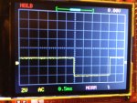
Here is the code I'm working with now (still some work to do). This works reasonably well and would work superbly (I guess) with a decent size robot, where the distance between the sensor and the front axle would be more than my mere 7 millimeters. Below is a picture from the scope for timing the line calculation part.

Code:
#include "Data.basinc"
#include "Math.basinc"
#include "LineSensor.basinc"
#include "SteerMotor.basinc"
#include "Debug.basinc"

#picaxe 40x2
#no_data
#no_table

setfreq em64              

'Outputs
Symbol CLK = C.1            'Clock - 5kHz ... 8 MHz
Symbol SI = B.2             'Signal In pin of the sensor
Symbol LED = B.5            'Sensor light LED

Symbol DIR = D.0            'DIR input, STSPIN220
Symbol EN = D.2             'EN output/input STSPIN220
Symbol STBY = D.3           'STBY output/input STSPIN220
Symbol STCK = D.7           'CLOCK input, STSPIN220
Symbol MODE2 = D.4          'MODE2 input, STSPIN220
Symbol MODE1 = D.5          'MODE1 input, STSPIN220

Symbol LED_A0 = A.0         'Line position LED display A0 pin
Symbol LED_A1 = A.1         'Line position LED display A1 pin
Symbol LED_A2 = A.2         'Line position LED display A2 pin

'Inputs
Symbol pinAO = pinB.1       'Analog out of the sensor

'Byte variables
Symbol pixel_data = b4      'Data from sensor [memory for testing]
Symbol pixel_mask = b5      'Decoded 8 pixel data
Symbol line_edge = b6       'Rightmost edge of the line
Symbol line_width = b7      'Width of the line in 16th of the total width
Symbol line_centre = b8     'Centre of the line
Symbol counter = b9         'Just a counter
Symbol LED_mask = b10       '3 to 8 encoder mask for line position LED display

'Word variables
Symbol Tint = w27           'Integration time adjustable part
Symbol Vout = w26           'Voltage on AO pin
Symbol EVout = w25          'Voltage on AO pin error, deviation from Vtarget
Symbol ELine = w24          'Line position error
Symbol OldELine = w23
Symbol line_state = w21     'Sensor output, normalized to fit into 16bit word
Symbol PLine = w20
Symbol ILine = w19
Symbol DLine = w18
Symbol steer_input = w17
Symbol agr_error = w16
Symbol line_pos = w15       'Position of the line centre with 16 position resolution
Symbol d_error = w14
Symbol line_pos_index = w12 'Line position index for line position LED display

'Constants
Symbol Vtarget = 194        'Target voltage on AO pin, two's complement, so actually 60
Symbol KpEVout = 30         'P coefficient/multiplier for Vout error correction
Symbol KpELine = 52         'P coefficient/multiplier for line position error correction
Symbol KiEline = 1            'I coefficient for line error corrections
Symbol iCap = 2000          'Cap I term at this value to prevent integrator wind-up
Symbol KdEline = 335        'D coefficient for line error corrections

Symbol MELine = 1          'Error multiplier to scale error up
Symbol InputDiv = 20        'Input divider to go down to reasonable value for number of steps for the motor
Symbol LinePulse = 10       'Line sensor clock pulse length for reading capacitor charge

init:
  low SI                    'Initialize SI pin low
  low STBY                  'Initialize low just in case
  low MODE1                 'All four inputs low for full step mode
  low MODE2
  low DIR
  low STCK
  high STBY                 'STBY high to register state of mode pins
  low EN                    'Keep EN low to save power when no steering needed
    
  pwmout LED, 399, 100      'Run two sensor light LEDs (<5mA) with ~25% duty
  
  steer_input = 0

  LoadData           'Load the lookup table and sample data into memory, variable just because of syntax
  
main:
  CalExposure        'Try to adjust exposure to the lighting conditions, variable just because of syntax
  do
   ReadLineData128
   low C.7
   GetLinePos(line_state)

;  ScaleEline                                               'Scale error up

  GetSignedPLine
  agr_error = agr_error + ELine                      'Ad up error for I term
  GetSignedILine
  d_error = ELine - OldELine                          'Calculate error trend
  GetSignedDLine
  OldELine = ELine                                       'Set the old error the current error

  GetSteerInput

  high C.7
  RunSteeringStepper(steer_input)

;   RunLineLEDs    
;   ShowLine                            'Testing purposes only
;   ShowData                            'Show the string of ones and zeroes in the terminal
  loop
goto main
IMG_2240.JPG

Am I measuring something wrong?

Edmunds
 
Last edited:

hippy

Technical Support
Staff member
I'm not sure I'm following the 'problem' of this thread anymore, but if it is still about finding the center of the line from 128px wide data then how do you get so big numbers?
There isn't a problem per se; it was just my take on how to create a 'centre of line' algorithm. Then came discussion on alternatives for how to determine that; averaging and finding the median.

I'm not entirely sure how you mean by 'big numbers' but if you mean the length of time being taken that is down to running at 32MHz, reading 128 bits data, handling that on the fly, and/or putting them in scratchpad and then performing the algorithm.

For example the high period on B.7 of the code below is measured with a logic analyser at 41ms, the low at 25ms which is correct for a a PAUSE 100 at 32MHz, four times the speed of the default 8MHz ...

Code:
#Picaxe 28X2
SetFreq EM32
Do
  High B.7
  For ptr = 0 To 127
    @ptr = pinA.0
    PulsOut C.0, 1
  Next
  Low B.7
  Pause 100
Loop
So that gives the time in which digital data for 128 pixels can be placed in scratchpad at 32MHz. That would be nearer 20ms at 64MHz.

Unrolling the FOR-NEXT loop to 128 "@ptrInc = pinA.0 : Pulsout C.0, 1" reduces the time to 20ms at 32MHz, which would be 10ms at 64MHz. That would improve my reading data and running the edge detection algorithm speed to give a full loop time of 33ms at 32MHz, 16ms at 64MHz, but isn't a technique suited to calculating average or median on the fly.

I am not sure what you are measuring or if you are measuring it wrongly. Perhaps post your full code and I can run it on my chip to see what time I measure. If you are reading fewer than 128 pixels, or not processing all those pixels within your algorithm, yours would be quicker.
 
Last edited:

edmunds

Senior Member
Dear @hippy,

With 'problem' I meant a 'task' or something like that, not a problem as in something bad :). I don't quite get what is the difference between median and average if there is one.

Yes, I meant timing numbers. I get a magnitude smaller values and this sounds strange. As I really do want to understand how much time does it take for future calculations, I would like to sort this out. Thus the question.

I will pack and send up all the files.


Thank you for your input,

Edmunds
 

Attachments

Last edited:

hippy

Technical Support
Staff member
Median is the middle number. Say you have ten sensor pixels (0-9), pixels 1,2,6,7,8 are set, "-12---678-", the average is (1+2+6+7+8)/5 = 4.8. The median puts all the numbers together "12678" and chooses what's in the middle, 6 six in this case.

For a larger set of numbers and fewer noise pixels the median should, in theory, provide a better centre of line determination than an average.

I'll take a look at your code, but here's my test harness which fakes a sensor reading so 0-9 are clear, 10-42 are set, 43-128 are clear. At 32MHz that 'reading the sensor' and determining median on the fly takes 67ms. The edge detection takes 12ms, a total of 79ms. Which would be 40ms at 64MHz.

Code:
#Picaxe 28X2
#Terminal 38400
#No_Table
#No_Data

; ===== SENSOR INFORMATION =====

Symbol SENSOR_WIDTH = 128
Symbol LINE_WIDTH   = 32

Symbol MIN_SENSOR   = 0
Symbol MID_SENSOR   = SENSOR_WIDTH / 2
Symbol MAX_SENSOR   = SENSOR_WIDTH - 1

Symbol LFT_SENSOR   = MIN_SENSOR + LINE_WIDTH 
Symbol RGT_SENSOR   = MAX_SENSOR - LINE_WIDTH 

Symbol LINE_HALF    = LINE_WIDTH / 2

; ===== VARIABLES =====

Symbol reserved     = w0 ; b1:b0

Symbol lftPixel     = w1 ; b3:b2
Symbol midPixel     = w2 ; b5:b4
Symbol rgtPixel     = w3 ; b7:b6
Symbol offCentre    = w4 ; b9:b8

Symbol medPixel     = w5 ; b11:b10 - Median

Symbol ledDisplay   = b12

; ===== INITIALISATION =====

SetFreq EM32

; Clear the pixel buffer

For ptr = MIN_SENSOR To MAX_SENSOR
  @ptr = 0
Next

; Add the no line detection marker so we will
; stil find gind a match even if no sensor
; data.

@ptrInc = 0
@ptrInc = $FF
@ptr    = $FF

; ===== MAIN PROGRAM =====

Do

  ; ----- Fake read the sensor -----

  High B.7

  ; And Determine median on the fly

  reserved = $100
  For ptr = MIN_SENSOR To MAX_SENSOR
    If ptr < 10 Or ptr > 42 Then
      @ptr = 0
    Else
      @ptr = $FF
      Put reserved, $FF
      reserved = reserved + 1
    End If
  Next
  ptr = reserved - $100 - 1
  If ptr0 = 0 Then
    ptr = ptr / 2
    medPixel = @ptr
  Else
    ptr = ptr / 2
    medPixel = @ptrInc + @ptr / 2
  End If

  Low B.7

  Pause 1  

  ; ----- Determine edges -----

  High B.7

  ; Find the lowest leftmost pixel

  ptr = MIN_SENSOR
  Do
    Do : Loop While @ptrInc = 0
  Loop While @ptrInc = 0
  lftPixel = ptr - 2

  ; If past the sensor data we found the 
  ; catch-all marker

  If lftPixel > MAX_SENSOR Then
    Low B.7
    SerTxd( "No line found", CR, LF )
  Else

    If lftPixel > RGT_SENSOR Then
      ; Line is off to the right so we guess
      ; at where the rightmost pixel wll be
      rgtPixel = lftPixel + LINE_WIDTH
    Else

      ; Find the highest rightmost pixels

      ptr = MAX_SENSOR
      Do
        Do : Loop While @ptrDec = 0
      Loop While @ptrDec = 0
      rgtPixel = ptr + 2      

      If rgtPixel < LFT_SENSOR Then
        ; Line is off to the left so we make
        ; a guess as to where leftmost really
        ; would have been
        lftPixel = rgtPixel - LINE_WIDTH
      End If

    End If

    ; Deterimine mid point pixel of line

    midPixel = rgtPixel - lftPixel / 2 + lftPixel

    ; Determine how far away from centre of sensor

    offCentre = midPixel - MID_SENSOR

    Low B.7

    ; ----- report results -----

    SerTxd( "L"   ) : reserved = lftPixel  : Gosub Show
    SerTxd( "M"   ) : reserved = midPixel  : Gosub Show
    SerTxd( "R"   ) : reserved = rgtPixel  : Gosub Show
    SerTxd( "OFF" ) : reserved = OffCentre : Gosub Sign

    ; Report by how much the median diverges
    ; from the calculated mid point

    reserved = medPixel - medPixel
    SerTxd( "MED" ) :                        Gosub Sign

    reserved   = LINE_WIDTH * 2 + SENSOR_WIDTH
    ledDisplay = reserved / 2 + offCentre * 7 / reserved Max 6

    SerTxd( "LED=" )
    For reserved = 0 To 6
      If reserved = ledDisplay Then
        SerTxd( "#")
      Else
        SerTxd( "-")
      End If
    Next
    SerTxd( CR, LF )

  End If
Loop

; ===== NUMBER DISPLAY =====

Sign:
  If reserved > 0 And reserved < $8000 Then
    SerTxd( "=+", #reserved )
    Goto Pad
  End If

Show:
  If reserved < $8000 Then
    SerTxd( "=", #reserved, " " )
  Else
    reserved = -reserved
    SerTxd( "=-", #reserved )
  End If

Pad:
  Select Case reserved
    Case < 10  : SerTxd( "   " )
    Case < 100 : SerTxd( "  "  )
    Else       : SerTxd( " "   )
  End Select
  Return

; ===== END OF PROGRAM =====
 

edmunds

Senior Member
Thanks @hippy,

It is difficult to see why median would be better with a naked eye, but I believe you :). Anyway, the big difference between the 'take' on this is the lookup table, if you remember. For line center part, I never have to do full 128 iterations of anything. I do 128 once to read data from the sensor, but that I would have to add on top of your code anyway, so I did excluded this from the measurement. Looking at the code now, I think I have 'cheated' with 15 reads from EEPROM. If I put those back in between the pulses, I'm at 7ms for finding where the line is minus high and low commands.

Edmunds
 

edmunds

Senior Member
I have measured some more now and it seems average full loop with correction takes less than 20ms with maximum going to 40ms for correction from full left to full right or backwards. Is updating 50 times per second a lot? Or not a lot? No idea at the moment, but this is something to think about.

Edmunds
 

hippy

Technical Support
Staff member
Yes, I meant timing numbers. I get a magnitude smaller values and this sounds strange. As I really do want to understand how much time does it take for future calculations, I would like to sort this out. Thus the question.
It basically comes down to how many pixels you are processing. I am storing all 128 readings in scratchpad and using all those to determine the centre of line reading. You are reading 128 readings but packing them into a single word as 16 bits, then doing your centre of line determination on just that. That in theory should be a lot quicker.

At 32MHz, my reading 128 pixels and calculating median = 67ms. Your reading 128 pixels and creating a 16-bit word is slightly less at 60ms.

My centre of line determination takes 13ms, yours takes just 1.6ms.

So my reading and determining loop time at 32MHz is 80ms, yours about 62ms. 40ms and 31ms at 64MHz.

But your effective 'off the centre of line' resolution is -7 to +7, mine is -80 to +80. If I use only every other pixel, -40 to +40 resolution, my sample time drops to 33ms and edge detection time to 7ms, a total of 40ms at 32MHz, 20ms at 64MHz.

So, at 64MHz ...

Your 15 step resolution reading (30ms) and calculating (1ms) = 31ms
My 80 step resolution reading (16ms) and calculating (4ms) = 20ms
My 160 step resolution reading (34ms) and calculating (6ms) = 40ms

I would say the times you and I are getting are as would be expected, are all roughly in the same ballpark. There are probably optimisations which could be had in your code to speed things up.

Note that none of the measurements include sensor calibration or motor controlling times. Also my sensor readings are faked so the timing may not be entirely accurate.

I would say that optimising into a single word of 16 pixels isn't really that great a saving over storing 128 pixels in scratch pad, and may be less efficient than storing 64 pixels in scratchpad. That was a big unknown. I'm actually surprised there is not that much in it in overall terms of time taken.
 

edmunds

Senior Member
Dear @hippy,

Thank you for that analysis, very interesting. In theory, this is now the interesting part:

My 80 step resolution reading (16ms) and calculating (4ms) = 20ms
In practice, however, I'm not sure how well it would cope with noise. At the moment, I have no idea how noisy is data the algorithm is dealing with. I can output data string on terminal, but that is not very scientific. I might try some code to count the number of noisy vs not noisy bytes and store them in EEPROM over a circle on my test layout to read and analise them on a computer later on.

But your effective 'off the center of line' resolution is -7 to +7, mine is -80 to +80.
I have been thinking I could use 16 bits to either side, so I could double the resolution. However, this is splitting hairs if moved to the real environment as 15 point resolution is ~540um (0.5mm), 30 point resolution would be ~271um and 160 - ~51um (0.05mm). I cannot imagine 0.5mm resolution with 20 to 40 reads per second would not be able to guide a vehicle traveling at 0.14m/s. Or, so it seems.

There are probably optimisations which could be had in your code to speed things up.
That is another interesting part :).

I will now spend some time on integrating the calibration procedure into every loop, depending on what is seen, because I have a suspicion some of the instability I have comes from the fact the car looses the line because of changing light conditions.

Then, I want to look into non-linearity. Or, rather linearity of my current error calculation algorithm and suspicion my system cannot be described linearly and thus I cannot get rid of the final little wiggle on straight stretches.

I also want to make the car continue chasing the line if it was lost to a side.

Issues above are somewhat independent on how you arrive at the line offset, so I will address those and then try your code with the real sensor and steering.

Thank you for your time,

Edmunds
 

erco

Senior Member
"In theory there is no difference between theory and practice. In practice there is." Yogi Berra
 

hippy

Technical Support
Staff member
There are probably optimisations which could be had in your code to speed things up.
The following takes 13ms at 64MHz to read all 128 pixels digitally, and averages sets of 8 to give a 16-bit word result -

Code:
  For ptr = 0 To 15
    bit7 = pinA.0 : PulsOut C.0, 1
    bit6 = pinA.0 : PulsOut C.0, 1
    bit5 = pinA.0 : PulsOut C.0, 1
    bit4 = pinA.0 : PulsOut C.0, 1
    bit3 = pinA.0 : PulsOut C.0, 1
    bit2 = pinA.0 : PulsOut C.0, 1
    bit1 = pinA.0 : PulsOut C.0, 1
    bit0 = pinA.0 : PulsOut C.0, 1
    Read b0, b1
    line_sensor = line_Sensor << 1 | b1
  Next
Given that averaging of 8-pixels should remove any noise pixels it seems it should not be necessary to worry about noise after that, the left and right edges can easily be found in a couple of instructions so all-in you should be able to read your 128 pixels and find the centre of the line in the 16-bit word in around 14ms.

So reading pixels digitally is quicker than analogue; one just needs to do it efficiently.
 

hippy

Technical Support
Staff member
Why not ? Any variable could be used and ptr isn't being used for anything else at the time. Reality is it is just a hang over from other code from which this derived which was storing all 128 bits of data in scratchpad as 16 bytes.
 

edmunds

Senior Member
Why not ? Any variable could be used and ptr isn't being used for anything else at the time. Reality is it is just a hang over from other code from which this derived which was storing all 128 bits of data in scratchpad as 16 bytes.
I was just thinking there was something special about it I did not understand. All cool, thanks.

Edmunds
 

hippy

Technical Support
Staff member
Here's an option to read all 128 digital pixels and calculate the median and the offset of the line from the centre of sensor on the fly. I can't find what I wrote down at the time but I recall it took 14ms at 64MHz.

Code:
Symbol n = b1
Do
  ; Returns w0 = -15 to +15
  ptr = 0
  For n = 0 To 15
    bit7 = pinA.0 : PulsOut C.0, 1
    bit6 = pinA.0 : PulsOut C.0, 1
    bit5 = pinA.0 : PulsOut C.0, 1
    bit4 = pinA.0 : PulsOut C.0, 1
    bit3 = pinA.0 : PulsOut C.0, 1
    bit2 = pinA.0 : PulsOut C.0, 1
    bit1 = pinA.0 : PulsOut C.0, 1
    bit0 = pinA.0 : PulsOut C.0, 1
    Read b0, b0
    If b0 <> 0 Then
      @ptrInc = n
    End If
  Next
  If ptr = 0 Then
    SerTxd( "No line", CR, LF )
  Else
    If ptr0 = 1 Then
      ptr = ptr - 1 / 2
      w0 = @ptr * 2 - 15
    Else
      ptr = ptr - 1 / 2
      w0 = @ptrInc + @ptr - 15
    End If
    If w0 >= $8000 Then
      w0 = -w0
      SerTxd( "-", #w0, CR, LF )
    Else
      SerTxd( "+", #w0, CR, LF )
    End If
  End If
Loop
 

edmunds

Senior Member
This is actually quite brilliant. To use prt in this way. And uses only one word variable for the entire deal. I'm not sure this adds much to the speed as the calculation of line offset takes less than a millisecond anyway, but it is, sure, beautiful :).

Thanks,

Edmunds
 

hippy

Technical Support
Staff member
It improves the speed overall. What was 30ms reading plus 1 millisecond processing comes down to some 14ms total.
 

edmunds

Senior Member
Dear all,

To follow up on this, I have now managed to improve the algorithm to take 3.1ms instead of 16ms for sensor data read and line position calculation. Most of the improvement comes from using a single SHIFTIN command to store data in scratchpad and then rolling it backwards into a line_pos variable. I have eliminated the for loop to cut further 1.6ms off the total. I also replaced if then and setbit with fancy bitwise operations, but this is just for general coolness and me being proud I figured something like that out myself :) - no real time saving there to my surprise.

The result is, I have totally wobble-free travel of the car on straights. A new video is available here. The ugly connectors, switches and LEDs on the trailer are all prototyping equipment and will be gone from the final design.

While away, I have written approx. 1.6ms continuous calibration routine, but have not yet tested it. If it works, I would have a very robust line follower with the correction loop of sub-5ms.

Code:
#macro ReadLineData128()
  high SI : pulsout CLK, LinePulse : low SI   'Pulse SI to end the scan/start the next scan
  pwmout CLK, 1, 4                            'Clock out some fast pulses (8MHz @ 64MHz clock speed)
  pauseus Tint                                'Allow for sufficient integration time
  pwmout CLK, OFF                             'Stop the clock
  high SI : pulsout CLK, LinePulse : low SI   'Pulse SI to end the scan/start the next scan

  FourCLKPulses                               'Generate empty reads to ignore first 4 pixels
  GetLineState                                'Store pixels into line_state
  FourCLKPulses                               'Generate empty reads to ignor last 4 pixels
#endmacro

#macro FourCLKPulses()
  pulsout CLK, LinePulse                         'Pulse clock to start reading next pixel ...
  pulsout CLK, LinePulse                         'Pulse clock to start reading next pixel ...
  pulsout CLK, LinePulse                         'Pulse clock to start reading next pixel ...
  pulsout CLK, LinePulse                         'Pulse clock to start reading next pixel ...
#endmacro

#macro GetLineState()
  line_state = 0                                 'Set line_state to 0 to avoid clearing individual bits
'Shift sensor data into variables in location 56 to 70
  shiftin CLK, AO, 0, (@bptrinc,@bptrinc,@bptrinc,@bptrinc,@bptrinc,@bptrinc,@bptrinc,@bptrinc,@bptrinc,@bptrinc,@bptrinc,@bptrinc,@bptrinc,@bptrinc,@bptrinc)
  read @bptrdec, pixel_mask                  'Get pixel state from position 70
  line_state = line_state | pixel_mask << 1  'Set the bit in line_state if pixel_mask = 1 and shift left by 1 (will end up #14)
  read @bptrdec, pixel_mask
  line_state = line_state | pixel_mask << 1
  read @bptrdec, pixel_mask
  line_state = line_state | pixel_mask << 1
  read @bptrdec, pixel_mask
  line_state = line_state | pixel_mask << 1
  read @bptrdec, pixel_mask
  line_state = line_state | pixel_mask << 1
  read @bptrdec, pixel_mask
  line_state = line_state | pixel_mask << 1
  read @bptrdec, pixel_mask
  line_state = line_state | pixel_mask << 1
  read @bptrdec, pixel_mask
  line_state = line_state | pixel_mask << 1
  read @bptrdec, pixel_mask
  line_state = line_state | pixel_mask << 1
  read @bptrdec, pixel_mask
  line_state = line_state | pixel_mask << 1
  read @bptrdec, pixel_mask
  line_state = line_state | pixel_mask << 1
  read @bptrdec, pixel_mask
  line_state = line_state | pixel_mask << 1
  read @bptrdec, pixel_mask
  line_state = line_state | pixel_mask << 1
  read @bptrdec, pixel_mask
  line_state = line_state | pixel_mask << 1
  read @bptrdec, pixel_mask
  line_state = line_state | pixel_mask << 1
#endmacro
#macro GetLinePos(line_state)
'Determine the position of the line
  if line_state > 0 then                            'If there is any line at all ...
    line_width = NOB line_state                     '... find the number of set bits = line width ...
    line_edge = NCD line_state                      '... find the highest set bit = rightmost edge of the line ...
    line_centre = line_width / 2                    '... store half of the line in a new variable to save on number of operations
    select case line_edge                           'Cater for right and left side limits situations when not all of the line is seen ...
    case 1  : line_pos = line_centre                '... line dissapearing on the left side ...
    case 15 : line_pos = 15 - line_centre           '... line dissapearing on the right side ...
    else    : line_pos = line_edge - line_centre    '... both edges inside field of view
    endselect
    else
  endif
  select case line_pos                              'Maybe can be done faster, but takes us as it is
  case 1 to 7  : Eline = -8 + line_pos              'Set negative Eline from line_pos
  case 9 to 15 : Eline = line_pos - 8               'Set positive Eline from line_pos
  else         : ELine = 0                          'Set error to zero
  endselect
#endmacro

Cheers,

Edmunds
 

erco

Senior Member
Sweet and very smooth! You've got that baby all dialed in now. Congrats on sticking with it to a great solution!
 

hippy

Technical Support
Staff member
Excellent. You can probably reduce the execution time by half or more by replacing ...

Code:
  line_state = 0
  read @bptrdec, pixel_mask
  line_state = line_state | pixel_mask << 1
  read @bptrdec, pixel_mask
  line_state = line_state | pixel_mask << 1
  read @bptrdec, pixel_mask
  line_state = line_state | pixel_mask << 1
  read @bptrdec, pixel_mask
  line_state = line_state | pixel_mask << 1
  read @bptrdec, pixel_mask
  line_state = line_state | pixel_mask << 1
  read @bptrdec, pixel_mask
  line_state = line_state | pixel_mask << 1
  read @bptrdec, pixel_mask
  line_state = line_state | pixel_mask << 1
  read @bptrdec, pixel_mask
  line_state = line_state | pixel_mask << 1
  read @bptrdec, pixel_mask
  line_state = line_state | pixel_mask << 1
  read @bptrdec, pixel_mask
  line_state = line_state | pixel_mask << 1
  read @bptrdec, pixel_mask
  line_state = line_state | pixel_mask << 1
  read @bptrdec, pixel_mask
  line_state = line_state | pixel_mask << 1
  read @bptrdec, pixel_mask
  line_state = line_state | pixel_mask << 1
  read @bptrdec, pixel_mask
  line_state = line_state | pixel_mask << 1
  read @bptrdec, pixel_mask
  line_state = line_state | pixel_mask << 1
with ...

Code:
  read @bptrdec, bit15
  read @bptrdec, bit14
  read @bptrdec, bit13
  read @bptrdec, bit12
  read @bptrdec, bit11
  read @bptrdec, bit10
  read @bptrdec, bit9
  read @bptrdec, bit8
  read @bptrdec, bit7
  read @bptrdec, bit6
  read @bptrdec, bit5
  read @bptrdec, bit4
  read @bptrdec, bit3
  read @bptrdec, bit2
  read @bptrdec, bit1
  line_state = w0 & $FFFE
 
Top