Hi All
I am looking at interfacing the 40x2 with a DS1307 and sparkfuns HTU21D breakout board through sparkfuns bi-directional logic level
convertor.
I take no credit for the code which was writen by Marks in another post for the HTU21D that I found on the forum, I mearly altered
the variables used and added a bit of rounding up and down to it and the reading writing to the ds1307.
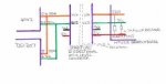
My main question is in regards to the pullup resistors to the 2 I2cs.
I propose using the pullup resistors on the sparkfun 21d board for the comunication lines with the relivent addresses to the I2c being read.
Will this work or do I have to also put in place the pullup resistors on the 5V side.
The code is as follows
regards
john
I am looking at interfacing the 40x2 with a DS1307 and sparkfuns HTU21D breakout board through sparkfuns bi-directional logic level
convertor.
I take no credit for the code which was writen by Marks in another post for the HTU21D that I found on the forum, I mearly altered
the variables used and added a bit of rounding up and down to it and the reading writing to the ds1307.
My main question is in regards to the pullup resistors to the 2 I2cs.
I propose using the pullup resistors on the sparkfun 21d board for the comunication lines with the relivent addresses to the I2c being read.
Will this work or do I have to also put in place the pullup resistors on the 5V side.
The code is as follows
Code:
symbol modetop=1  'markers for the diffrent program areas
symbol modemain=2
symbol modevalue=3
symbol modetime=4
symbol modepins=5
symbol modeupdate=6
symbol modeupdate1=7
symbol modeupdate2=8
symbol modeupdate3=9
symbol modertcset=10
symbol modepinset=11
symbol modeset=12
symbol modeprog=13
symbol modework=14
symbol modedelay=15
symbol modeweek=16
symbol modeexchange=17
symbol modewriten=18
symbol modestore=19
symbol modedetermine=20
symbol modefan=21
symbol modehumdry=22
symbol modehumwet=23
symbol modescratch=24
symbol modealarm=25
symbol modereturn=26
'**************************************************************************************
symbol usbon=b1   ' Data storage on or off
symbol pointer=b2  'setpointer and equipment selection in keypad
symbol marker =b3      'b5 interupt marker between program slots
symbol themode=b4  'program location pointer
'***********************
symbol heaton=b5  'Attached Equipment on or off area obtained via keypad
symbol dehum=b6
symbol humon=b7
symbol air=b8
'*************************************
'TEMPRETURE
symbol vT = b9 	' the preset value for Temperature obtained from keypad
symbol vC=b10   'for setting night tempreture if diffrent tempreture required
symbol NvT=b11    'night tempreture value
symbol Dry=b12    'tempreture value from sensor
symbol Dry1=b13   'tempreture differental used to evaluate outcome
symbol Dry2=b14    'tempreture differental used to evaluate outcome
'**********************************************************
'RHIDITY
symbol ii=b15  'counter used for sensor readings
symbol fr=b16   'Emergancy stop
'*******************************
symbol vHl=b17      '  the preset value for RHidity minimum value via keypad
symbol vH = b18 	' the value maximum for RHidity via keypad
symbol RH=b19      ' RHidity value obtained from sensor
'****************************

symbol TempW = w10	;b21 + b20 used for calculations for all sensors
symbol temp2=w11 'uSD write end b23 +b22
symbol temp_byte=b24

symbol photo=b25     'light sensor
symbol equip=b26   'On / off times for pins D.3,D.2,D.1,D.0
symbol volt=b27   'Fan speed
symbol line=b28  'VARIABLES FOR uSD for line feed in excel


'*********************************************************************************************
'SETTING VARIABLES FOR DS1307
symbol datebcd=b29
symbol monthbcd=b30
symbol yearbcd=b31  'Variables from keypad converted at SetRTC to BCD
symbol daybcd=b32    'Loaded into the DS1307
symbol hourbcd=b33
symbol minbcd=b34
symbol secbcd=b35
'******************************************************************
'PICAXE VARIABLES FOR CONVERTED VALUES FROM I2C CLOCK
symbol sec =b36
symbol hour=b37
symbol mins=b38  'Read back variables from the DS1307 using the DS1307 as the
symbol day=b39   'Timer for the Data Logging and Display
symbol month=b40  'hour = hourbcd / 16 * $FA + hourbcd Hippy's solution for BCD to Dec conversion
symbol year=b41
symbol date=b42
'********************************************************************************
symbol Tdry=w23 symbol TEMPmsb=b47 symbol TEMPlsb=b46
symbol Hum=w24   symbol RHmsb=b49 symbol RHlsb=b48


SYMBOL Sign = b50

'**********************
symbol TD4=b33
symbol TD3=b32
symbol TD2=b31
symbol TD1=b30
symbol TD0=b29
symbol control=$10 ' sets RTC

symbol hi2c =C.3 ' 40x2 pin conection for DS1307 and HTU21D


#picaxe 40x2
	hi2csetup i2cmaster, %11010000, i2cslow_8, i2cbyte


  		hi2cin 0, (secbcd,minbcd,hourbcd)    'READ RTC
         		 hour = hourbcd / 16 * $FA + hourbcd
    		 mins = minbcd / 16 * $FA + minbcd
      		  sec = secbcd / 16 * $FA + secbcd
  		pause 500
main:
	do

	hi2csetup i2cmaster, %11010000, i2cslow_8, i2cbyte

     		do
		hi2cin 0, (secbcd,minbcd,hourbcd)    'READ RTC
         		 hour = hourbcd / 16 * $FA + hourbcd
      		 mins = minbcd / 16 * $FA + minbcd
      		  sec = secbcd / 16 * $FA + secbcd

    		pause 800
		peek 80,@bptr
 		loop until mins<>@bptr

hi2csetup i2cmaster,0x80,i2cslow_8,i2cbyte ' %10000000 (hex 0x80) is device i2c bus address
Pause 20
hi2cin 0xE3, (TEMPmsb,TEMPLsb) : TEMPLsb = TEMPLsb AND 0xFC ' Last bits of LSBdata ,
Pause 20
hi2cin 0xE5, (RHmsb ,RHlsb ) : RHlsb = RHlsb AND 0xFC ' must beset to ?0? before calculating
pause 20

Calculate_Temp: ; TempActual = TempSensor /65536 x175.72 -46.85
Tdry = Tdry **17572 -4685 ' -40.00 to 125?C 14bit
Sign = " " ' Display +
IF Tdry > 13000 THEN
Sign = "-" ' Display -
Tdry = -Tdry
ENDIF
BinTOASCII Tdry,TD4,TD3,TD2,TD1,TD0
IF TD4 = "0" THEN : TD4 = " " ' leading zero blanking
IF TD3 = "0" THEN : TD3 = " " : ENDIF ' leading zero blanking
ENDIF
'sertxd ( " Temperature ",Sign,TD4,TD3,TD2,".",TD1,TD0,"?C",cr,lf)
dry= TD3-48*10
dry=dry+TD2-48
TD0=TD0-48
TD1=TD1-48
if TD0>=5 then
TD1=TD1+1
endif
if TD1>=5 then
dry=dry+1
endif
'sertxd ("DRY=",32,#dry,cr,lf)

RH_Compensated:
Tdry =Tdry /10 ; RHcompensated = RHactual + (25 -TempActual) x -0.1
IF Sign = "-" THEN : Tdry = -Tdry : ENDIF ' improves RHaccuracy over 0.00 to 80.00?C


Calculate_RH: ; RHactual = RHsensor /65536 x125 -6
Hum = Hum **12500 -600 + Tdry -250 ' -6.00 to 118 Rh% 12bit
Sign = " " ' Display +
IF Hum > 13000 THEN
Sign = "-" ' Display -
Hum = -Hum
ENDIF

BinTOASCII Hum,TD4,TD3,TD2,TD1,TD0
IF TD4 = "0" THEN : TD4 = " " ' leading zero blanking
IF TD3 = "0" THEN : TD3 = " " : ENDIF ' leading zero blanking
ENDIF
'sertxd ( " RHcompensated ",sign,TD4,TD3,TD2,".",TD1,TD0,"%",cr,LF)
RH=TD3-48*10
RH=RH+TD2-48
TD0=TD0-48
TD1=TD1-48
if TD0>=5 then
TD1=TD1+1
endif
if TD1>=5 then
RH=RH+1
endif
sertxd(#hour,32,":",#mins,cr,lf)
sertxd ("DRY=",32,#dry,"C",32,"HUMIDITY=",32,#RH,"%",cr,lf)
poke 80,mins
'for b0=0 to 10
 'Pause 2000
'next b0
loopjohn