Miniature line follower, final strech

edmunds

Senior Member
Dear all,

Here is a little video I shot today if how my line follower behaves. It basically manages a few corrections in the right direction, progressively overshooting until it cannot return anymore. The steering seems fast, powerful and precise, when I disconnect the line following code.

I have tried different proportional coefficients (PID) - multipliers for the error and I basically get the same sort of error. I could now go and try to add the I component (PID), but if I understand the theory correctly, it is unlikely to help. I should be able to navigate the line anyway, albeit oscillating. Or am I wrong?

Has anyone seen a line follower act like this and knows the cause and solution?


Thank you for your input,

Edmunds
 

Buzby

Senior Member
If you repeat from the same starting point, does it always do exactly the same ?
 

edmunds

Senior Member
If you repeat from the same starting point, does it always do exactly the same ?
No, but I'm guessing this is because before I put it on the line, I try to adjust the wheels to be straight. The reality is they must be more straight one time than another.

Edmunds
 

Buzby

Senior Member
A few seconds into the video the car is fully off the track, and it turns left ( i.e the correct way ), but later it is fully off again on the opposite side, but still turns left.

Are you sure the steering mechanism is 100% characterised ?

Have you programmed a fixed route ( i.e no line following ) and checked that the car performs exactly the same each time ?.
It doesn't matter what that route is, just that the car is repeating exactly the same each time. For a test like this you don't need the wheels straight to start with, having them fully left or right means you have a known starting point.

I'm very impressed with the car, it will be really cool when you have a few of them trundling around !.

Cheers,

Buzby
 

erco

Senior Member
Good start. You're not travelling fast enough to worry about I or D, so I suggest you delete those calcs from your program and focus only on P. IIRC this is your 128-bit sensor, which is challenging to read quickly, so my guess is that you're not sampling and correcting fast enough. As someone suggested in another thread, you might consider using only a portion of the sensor, at least to simplify at the start.
 

stan74

Senior Member
I think it's getting too complicated. How fast can the scanner scan all pixels into ram, work out 1st if the line is in the left no limits and steer left or in the right no limits and steer right. I wish I had one, it seems so simple. 128 analogue samples mount up. The pixel on/off seemed a more logical approach. As erco said " Does it go straight?" Pity you can't use 3 thin wires to sertxd what's happening.
 

edmunds

Senior Member
Thank you guys for your input. I'm sorry to report I made 8 LED line indicator and was adding it to the car, but something went wrong and the sensor stopped working. I tried all the obvious solutions and they have not worked, so I will have to check everything thoroughly and that requires undoing and unsoldering a lot of things. Will take some time.

Edmunds

EDIT: Sometimes disabling #no_data instruction helps a great deal when you have code dependent on data loaded in memory :). So all sorted before anything was seriously re-done, but bedtime now.
 
Last edited:

AllyCat

Senior Member
Hi edmunds,

I'm glad there was no damage to your hardware. ;)

You're not travelling fast enough to worry about I or D,
That is probably true for differential steering (and stepper motor drive) but I'm not sure that it is for Ackermann steering. For this case, I'll consider the system logically and not get bogged down in the maths:

Of course first you need to ensure that the control loop has negative feedback (i.e. if the line is to the Left of the car's centreline then normally the steering should turn to the left). But so many factors can affect this (e.g. the sensor, lens/pinhole, algorithm, stepper coils polarity and steering hardware, etc.) that it's probably easiest to just "toss a coin" and later introduce an inversion if the hardware works incorrectly. :)

HOWEVER, suppose that the line is to the left, but the car is already steering left. It may be that you don't need to turn the steering any further to the left, or maybe even turn to the right! That's the I in the maths.

Now suppose that the line is to the left, but is not as far left as for the previous scan. Again it may be that you actually need to turn the steering to the right, to avoiid overshooting the line. That is the D in the maths.

The other issue you must avoid is having too much "gain" (amplification) in the loop, and generally avoiding instability. The "easy" way to make a feedback loop stable is to ensure that it has a "dominant pole", i.e. there is one specific part in the loop which is much slower than all of the other components. In an electronic amplifier it's often a "bloody big capacitor" forming a low-pass filter (the dominant pole). In your steering control loop, it might be either the sensor (including the data acquisition), the steering algorithm, or the steering mechanism itself. Probably the mechanical steering is the slowest part, so the aim would be to make the other (software) elements work as fast as possible.

The problem with a "dominant pole" is that the system responds rather slowly (maybe too slowly) which is why feedback/control systems often use more sophisticated methods such as "feedforward", "phase advance" or PID. This may well be necessary in your system because of another assumption of basic control sytem/feedback theory is that the system is "linear", i.e. it will behave the same way regardless of how large the control signals are. But your system has severe limits, in particular the width of the sensor and the extent of the steering geometry (minimum turn radius).

Cheers, Alan.

PS: I've got my little (20 pence) 6mm stepper motor running from the (20 pence) audio amplifier module, as discussed in another thread (I'll add to that thread when appropriate). The torque is rather low (it's only consuming around 250 mW) but maybe it's just about enough to drive my "car". I think I've now worked out how to implement the 10 - 15 mm diameter wheels, so perhaps it's time to start building a "chassis". ;)
 

erco

Senior Member
Thanks, good catches, Buzby & Allycat.

Yes, from a quick glance at the video in the OP I assumed it was differential steering. If it is Ackerman steering then your best bet is to move the sensor with the steering a fixed distance ahead of the wheels, as done on my trike:


edmunds

Senior Member
Alan,

Thank you, this is brilliant stuff and I believe I even have some proof for your hypothesis.

@erco,

Thank you for the video, but moving the sensor further to the front is not an option. The sensor is as far forward from the wheels as possible for the model to stay a model. That is just a few millimetres, I know :).

I will get back to this thread with a new video of the car now with a LED array showing where it believes the line is ASAP, which is likely in a few hours.

Edmunds
 

edmunds

Senior Member
Dear all,

Here is the video as promised. I could not get better visibility of the LED array in the video, but the important part is the speed with which the LEDs change if compared to the speed the wheels react. With terminology used by Alan above, clearly my wheels are the 'dominant pole'. On top of that, with the algo I have now (file attached below) even if the car is already driving towards the line, since the only thing I'm looking at is, where the line is, I continue pushing towards it. As a result, instead of reducing the steering angle to become careful not to overshoot, I continue turning.

With every line crossing iteration, I'm crossing the line progressively faster (under greater angle) and by the time I start steering back towards the line, I'm long gone into stratosphere.

On top of that, one of the reasons I seem to be chasing my own tail here is the unavoidable consequence of using a stepper motor. The more of a correction I order, the longer it takes. Correcting with one revolution of the motor takes 10 pulses and, say, 10 time units because I have to provide all the 10 clock signals. If I want 10 revolutions, because I'm far out from the centre of the line I panic and order 100 pulses. But now it takes 10 times more time, before I can go back and check the sensor if this actually helped. This is contrary to a servo, where you send a command and forget about it no mater how far the servo has to travel to execute. Obviously, this is only a theoretical problem and true if even the slowest response is too slow for the speed I want to travel with, but at this point I cannot be sure this is or is not the case.

I will try to implement I and D terms now.

Alan, thanks again for your excellent practical explanation of I and D terms for this situation. Schools give you all the algorithms with integrals and derivatives, but then one has to go back and implement it in 8 bit micro without floating point operations, not MatLab :).

View attachment LineFollowerCarTest20170103.bas

Thank you everybody else as well,

Edmunds
 

stan74

Senior Member
I tried small geared stepper motors but apart from needing a separate picaxe to run them I thought they were to slow.With the same 6 port sequence only in reverse to reverse the motors, they turned more 1 way than the other for the same number of pulses, so I did something wrong. Motor speed is irrelevant. Straight lines no prob if it drives straight. Curves might mean more sensors triggered so keep the sensor array 90 degrees to line. I ordered a sensor array,it's building a small chassis that's difficult with few tools,materials,etc. Continuous servos in the post but how do I change their speed to steer? I've never used one. I would need setfreq m1 to get pwm as low as 60 Hz.I suppose I could make a trike. I had two 3 wheel cars as a teen. You can drive them with a motor bike licence in the UK.
 

Buzby

Senior Member
Hi Edmunds,

I've not studied your code closely, so I'm not sure what I'm about to say is already handled.

It looks like you are sending a large number of 'left' pulses to correct a large 'right' error, and a smaller number of 'left' pulses if the 'right' error is small.

Imagine the following scenario :

1st pass of main loop, car has big 'right' error, you perform large 'left' correction.

2nd pass of main loop, car has small 'right' error, ( i.e getting back closer to line ) you perform small 'left' correction.

But because it's a stepper motor, not a servo motor, you have actually performed two additive commands 'left', one large and one small, thus steering the wheels the right direction, but turning too far.

If this is how your code works it might explain the behaviour you see.

( If you have accounted for this please accept my apologies. )

Cheers,

Buzby
 

stan74

Senior Member
Hi Edmunds. I looked at your code but it was to complicated for me. I used a sub to pulse my steppers. A var for speed and a counter in the sub that increased every call and returned until it was the same as the speed val then it would reset the counter and pulse the motor. I couldn't find your motors control.
 

Buzby

Senior Member
Stan,

Edmunds is not using two steppers, just one driving an Ackermann steering mechanism.

Cheers,

Buzby
 

erco

Senior Member
I didn't realize you were using a stepper motor. IMO that's the straw that is breaking this camel's back. If ever a servo could save the day, it's here. Faster, simpler, fewer wires, less power, self-centering, better in every way. Is that an option, edmunds?
 

techElder

Well-known member
I believe edmonds has said way back at the beginning somewhere that space is the limitation. He's trying to fit the drive/steering mechanism into something that doesn't look like a waddling duck. :D
 

stan74

Senior Member
"On top of that, one of the reasons I seem to be chasing my own tail here is the unavoidable consequence of using a stepper motor. The more of a correction I order, the longer it takes. Correcting with one revolution of the motor takes 10 pulses and, say, 10 time units because I have to provide all the 10 clock signals. If I want 10 revolutions, because I'm far out from the centre of the line I panic and order 100 pulses. But now it takes 10 times more time, before I can go back and check the sensor if this actually helped."
That's what confused me. I can't see how changing speed has anything to do with steering unless he wants to drift round bends.
The motor IS tiny,smaller than the motor in a 9g servo I think erco.
 

erco

Senior Member
Some drastic changes are necessary in any case to speed up the steering response. The current system is unstable, oscillations (I hesitate to call them speed wobbles :) ) are increasing and this is in a straight line, the easiest possible scenario.

I still say changing to a servo steering or differential drive would be an infinitely more workable system. If there's no room for a 9g servo, there are smaller options.

http://www.ebay.com/itm/2PCS-1-5-g-Servo-Micro-Digital-Analog-Servo-Loading-Linear-Servo-Goteck-New-/222241393208

http://www.ebay.com/itm/MiNi-Micro-4-3g-Mini-Servo-for-Control-Aeromodelling-aircraft-flight-direction-C-/152344666331

@Tex: What's your beef with waddling ducks? :)
 

Buzby

Senior Member
Some drastic changes are necessary in any case to speed up the steering response.
Sorry erco, I disagree.

The mechanics are OK, but the algorithm is wrong.

The car can get back on track plenty fast enough, but it over-steers due to the correction being increased instead of decreased.
Look at the code. On each scan of the program the correction is increased further, even if the error has reduced.

There was talk of PID. This might be needed later ( well, PI anyway ), but until the P component is fixed nothing will work properly.

When edmunds gets the P working properly the car will stay on line, but sway over a small angle, more like a fish than a duck.

Cheers,

Buzby
 

edmunds

Senior Member
Nice discussion :). Thank you all for your inputs.

Buzby, I share your opinion and this is exactly what I think is wrong. Or, I can see it. Both, read in my own code and see the car acting.

Erco, you could still be right, but there is no way of knowing before I fix the software.

I tried to implement full PID yesterday. I think I succeeded sort of - I would still have to address integrator wind-up and figure out a threshold for that and maybe some more minor improvements, but it was not too bad already. The problem I realised after coding it all is that, at least the way I did it, it did not help a thing. Because I had two copies of it, one in the steer right case statement and the other one in steer left statement.

Since steer right in my case does not mean 'get the wheels over the centre, so they push the car to the right', but also 'if you steered left a lot and want to steer left less, issue some steer right', I need to be able to jump from steer left into steer right and back again. To reduce the input, I actually have to issue counter pulses i.e. turn the motor in another direction. My steering code structure is just completely wrong for that. So far, I have not figured out how to do this even in high level 'algorithm boxes with arrows' style. I will try to get some time to work on this today again, but this could take some thinking time.

Stan, I have removed all sub procedures for speed. I have tried my best to comment everything, but sorry if you found code confusing still. I understand it can be.

Edmunds
 

edmunds

Senior Member
I still say changing to a servo steering or differential drive would be an infinitely more workable system. If there's no room for a 9g servo, there are smaller options.

http://www.ebay.com/itm/2PCS-1-5-g-Servo-Micro-Digital-Analog-Servo-Loading-Linear-Servo-Goteck-New-/222241393208

http://www.ebay.com/itm/MiNi-Micro-4-3g-Mini-Servo-for-Control-Aeromodelling-aircraft-flight-direction-C-/152344666331
Dear Erco,

Thank you for the links. These are massive items however :). The only real servo option is here, but that shall remain the last resort. Most importantly, because of the fact I cannot control production of those.


Edmunds
 

edmunds

Senior Member
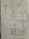
Came up with boxes and arrows. Maybe this is sufficient. Will try to implement in the software now.

IMG_2211.JPG

Edmunds
 

edmunds

Senior Member
This is now becoming real fun :).

I can now manage all the straight I have with the code executing the 'boxes and arrows' in post #27. On condition I set out reasonably straight. The quality of navigation is such, that I believe it could manage a straight or gentle curve indefinitely.

However, there is no sharp curve performance. Could this be because I'm considering the difference between the old and new error, but not the error itself? i.e. effectively doing I only? I believe so, but to implement this I'm bloody stuck with handling negative numbers, which is either two's complement or never ending selection statements :(. Huh. Will try.

Edmunds
 

Buzby

Senior Member
This is sounding good, let's see a video !.

I don't think you will need negative numbers, just a direction bits and magnitudes.
You can have a single macro called either if the car is too 'left or too 'right', with a direction bit and magnitude as parameters.

( Sorry, too busy to look at your code today, visitors in when I get home from work. )

Cheers,

Buzby
 

AllyCat

Senior Member
Hi,

... stuck with handling negative numbers, which is either two's complement or never ending selection statements :(.
My vote goes for twos complement maths, at least once you get the basic concepts and debugging sorted out:

Addition and subtraction work "automatically" with twos complement negative numbers, so you just need to ensure that you don't do direct multiplication or division, but instead call a subroutine (or macro) to perform the function. The subroutine/macro is quite simple, it just tests for a negative number (or both, if both can be negative), complements the negative number(s) to make them both positive and then performs the normal operator. Then it complements the result if one (but not both) of the input values had been negative.

Basically, you have (at least) three independent, signed input values (position of line, present direction of steering and whether the line is getting closer or further away). That gives (at least) 8 sign permutations and I believe all could occur, so you would need a large CASE statement. However, a single, signed mathematical calculation will give a positive or negative result, which immediately tells you which way (and by how much) to turn the steering. ;)

Cheers, Alan.
 

edmunds

Senior Member
Here comes another video. And the latest code attached below. I'm not sure I have all the algorithm right, it is pretty heavy by now, but after some initial success, I could not resist to try stabilising it with coefficients. I got the first stable results working with the difference between old and new error only, but I could not get the car to corner enough. Then I added the error itself and it destabilised everything, so I needed new coefficients, but cornering improved after all the adjustments. The turn you can see in the video is close to the limit of mechanical ability of the car. So if it is late to start turning, it is mechanically unable to 'catch the line' anymore. Equally, at the exit of the turn, the line disappears so fast, the car has no way of turning the wheels fast enough to stay on track - it should somehow start to correct back to straight sooner. At this point, I don't know if the problem is the speed of the system or algorithm or just coefficients or some mix of those. But will continue looking.


Edmunds

P.S. Sorry for fewer comments in the file, I will behave in the future again :).
 

Attachments

Last edited:

Buzby

Senior Member
My vote goes for no negative numbers at all, they're not needed in this application.

I've not got time to work it out exactly, but it all 'falls out' of the code that edmunds has hinted at in this 'lines and boxes' picture.

It might even be that he doesn't need maths at all !. I've got a feeling that if a few hours was spent fully characterising the relationship between radius of turn and stepper position then a much simpler solution could be found. Even just knowing the step number for 'straight' would be a great help.

Cheers,

Buzby
 

edmunds

Senior Member
My vote goes for no negative numbers at all, they're not needed in this application.

I've not got time to work it out exactly, but it all 'falls out' of the code that edmunds has hinted at in this 'lines and boxes' picture.

It might even be that he doesn't need maths at all !. I've got a feeling that if a few hours was spent fully characterising the relationship between radius of turn and stepper position then a much simpler solution could be found. Even just knowing the step number for 'straight' would be a great help.

Cheers,

Buzby
Well, Buzby, that would only work if a stepper would never miss a step. Since there is no absolute position indicator of sorts, a missed step would mean misalignment forever. While I'm doing pretty fat pulses now and I don't think any missed steps happen during normal operation, this can definitely happen. With a system that relies only on where the line is and being able to direct right or left, this would not be a problem. A system based on fixed number of steps would fail immediately. Also, there is (and is supposed to be) considerable freeway in the joints of steering mechanism. The exact steering angle will change even if the steering arm remains fixed. With all these uncertainties, as system that is somehow fixed and cannot adjust to its own error will fail.

Working out the steps is perfectly possible. Let me know if you really want to know :).

Edmunds
 

edmunds

Senior Member
Here is work in progress portion of the code that is new. Just if this is easier than opening the file. The drawback is you have to guess the variables :).

Code:
'New stuff
  if line_pos < 8 then                                         'off to the left
  	ELine = 8 - line_pos                                       '... by ELine much
  	E = E + ELine                                             'Error accumulator
  	ILine = E * KiELine / 100                             'I thing
  	KLine = ELine * KpELine / 10                       'K thing
  	if ELine < OldELine then                                'if progressing correctly
  	  low DIR                                                        'reduce the steering angle
  	  DLine = OldEline - ELine * KdEline / 10        'D thing
  	  steer_input = KLine + ILine + DLine
  	else                                                               'if still getting away from the line
  	  high DIR                                                      'increase steering angle
  	  DLine = ELine - OldELine * KdEline / 10       'D thing
  	  steer_input = KLine + ILine + DLine
  	endif
  elseif line_pos > 9 then                                  'off to the right
  	KLine = ELine * KpELine / 10
    ELine = line_pos - 9                                       '... by ELine much
  	E = E + ELine
  	ILine = E * KiELine / 100
    if ELine < OldELine then                                'if progressing correctly
    	high DIR                                                      'reduce steering angle
  	  DLine = OldEline - ELine * KdEline / 10       'D thing
  	  steer_input = KLine + ILine + DLine
  else                                                                 'if still getting away from the line
    	low DIR                                                       'increase steering angle
  	  DLine = Eline - OldELine * KdEline / 10       'D thing
  	  steer_input = KLine + ILine + DLine
    endif
  else                                                                 'do nothing
  	  ELine = 0
  	  E = 0
  	  steer_input = 0
  endif
  high EN                                            'Enable the device to steer, disable to save power and limit heat
  for Counter = 0 to steer_input           'Increase the number of loops to steer 'more' per cycle or decrease for 'less'
    pulsout STCK, 5000                        'About a minimum to get decent power
    pauseus 2500                                 'pauseus is double the length of pulsout, so half of pulsout time for a square wave
  next
  low EN
  OldELine = ELine     'Set the old error the current error
Edmunds
 
Last edited:

Buzby

Senior Member
Well, Buzby, that would only work if a stepper would never miss a step. Since there is no absolute position indicator of sorts, a missed step would mean misalignment forever. ..... as system that is somehow fixed and cannot adjust to its own error will fail.
It's not as black and white as that. When the car is moving 'on track' in a straight line, with only minor corrections, then you could reset a 'positioncount' variable to zero.
As the car encounters a bend and the stepper is given a few +/- corrections, those same values added to the positioncount give you an approximation of how many pulses are needed to get the steering straight again.

However, as I think on this more, I see it's not much help, as knowing how to set the wheels straight is one thing, getting them actually on the line is another.

But I still think it can be done without complex PID and negative numbers.

( I just wish I had a PE6<->Excel pipe working. It would be so much easier with a spreadsheet simulating the car, instead of my imagination. )

Your last video shows the code is getting better !.

Cheers,

Buzby.
 

edmunds

Senior Member
It's not as black and white as that. When the car is moving 'on track' in a straight line, with only minor corrections, then you could reset a 'positioncount' variable to zero.
As the car encounters a bend and the stepper is given a few +/- corrections, those same values added to the positioncount give you an approximation of how many pulses are needed to get the steering straight again.
True, could try that as well, but I doubt the totality of it would be any less complex than PID. A discrete time implementation of PID is not all that bad.

Edmunds
 

premelec

Senior Member
Looks from video you are getting there! If it isn't already in the code I'd put in a stop drive if no line is seen - perhaps with very slow subsequent search mode. Being a bicyclist I look forward to the bicycle version line follower - where you have to start turn right to turn left and such... I recall some full size oriental bicycle machines in parking lots on you tube... entertaining but not ready for prime time.
 

erco

Senior Member
edmunds: You're closing in, congrats! How fast is your steering, how many seconds from lock to lock (full left to full right)? If you can't speed that up any more, try slowing down your forward drive speed whenever the line is off-center. Maybe reduce speed proportional to how far off center. That will give your steering a chance to catch up.
 

edmunds

Senior Member
I'm a cyclist,2 electric. premelec https://www.youtube.com/watch?v=Z-WOXtQ9uH4
..but it's not following a line
It is likely, that the only thing that guy is showing off is being able to keep the balance. The antenna would suggest a radio transmitter with an operator nearby. If that is the case, it is likely a task doable with a picaxe. At least I'm about to try to do this with sort of sideways balancing based on accelerometer and gyroscope readings :).

Edmunds
 

premelec

Senior Member
There is a Physics Today article on Stability of Bicycles - reprinted Physics Today Sept 2006 p51-56 [from original PhyToday April 1970 p34-40]. It's great that bicycling works so well on decent geometry bike!
 
Top