Setting individual bits in scratchpad without nested FOR loops

edmunds

Senior Member
Dear all,

I have been trying to go from storing bytes to storing bits in scratchpad memory area. I need to store 128 pieces of ones or zeros in 16 bytes for better processing options later. I was storing 128 bytes before and that works. Now, with two nested FOR loops and an IF statement, which is the way I figured I could do individual bits, I'm too slow. At least that is the only way I can explain getting all zeros no matter what from the last 64 pixels of the sensor. The old code still works, so there is no electrical problem. Sorry for no comments on this one, but it is kind of simple.

Is there a magic better=faster way of doing this?

Code:
  pixel_data = 0
  for counter = 0 to 15
  	for counter2 = 7 to 0 step -1
          if pinAO = 1 then : setbit pixel_data, counter2 : endif
    	pulsout CLK, 10                                                 
  	next counter2
  	put counter, pixel_data
  next counter
If that does not work, is there a 'magic' way of converting 128 bytes with values 1 and 0 laying in scratchpad into 16 bits of a word variable?


Thank you for your time,

Edmunds
 

stan74

Senior Member
This would scan 128 pixels into 16 bytes.


Code:
[color=Purple]@ptr[/color][color=DarkCyan]=[/color][color=Navy]0[/color]
[color=Blue]for [/color][color=Purple]ptr[/color][color=DarkCyan]=[/color][color=Navy]0 [/color][color=Blue]to [/color][color=Navy]15
      [/color][color=Blue]for [/color][color=Purple]b0[/color][color=DarkCyan]=[/color][color=Navy]0 [/color][color=Blue]to [/color][color=Navy]7
            [/color][color=Purple]b6[/color][color=DarkCyan]=[/color][color=Navy]1 [/color][color=Green];scan  pixel 0 or 1 into b6
            [/color][color=Purple]b6[/color][color=DarkCyan]=[/color][color=Purple]b6[/color][color=DarkCyan]<<[/color][color=Purple]b0
            @ptr[/color][color=DarkCyan]=[/color][color=Purple]@ptr [/color][color=DarkCyan]or [/color][color=Purple]b6
            [/color][color=Blue]sertxd ([/color][color=Red]"bit "[/color][color=Black],#[/color][color=Purple]b0[/color][color=Black],[/color][color=Red]" ptr="[/color][color=Black],#[/color][color=Purple]ptr[/color][color=Black],[/color][color=Red]" @ptr="[/color][color=Black],#[/color][color=Purple]@ptr[/color][color=Black],[/color][color=Blue]cr[/color][color=Black],[/color][color=Blue]lf)
      next [/color][color=Purple]b0[/color]
[color=Blue]next [/color][color=Purple]ptr    [/color]
[color=Blue]end[/color]
That gives 8 words to check. The line is in the word that's not 0 or 65535.
You are on about line following,aren't you?
 
Last edited:

lbenson

Senior Member
It doesn't explain why you're getting all zeroes, but shouldn't "pixel_data = 0" be after "for counter = 0 to 15"? Since you are only setting bits, no bit in pixel_data which has been set in a previous iteration of the inside loop will ever be reset to 0.

I know it doesn't replicate your line data, but in simulation, the following program, basically using the logic of your code but with "pixel_data = 0" moved, produces varying bytes based on a random bit value.
Code:
' 20setbit
#picaxe 20x2
  symbol pinAO = bit15 ' just for testing
  symbol pixel_data = b2
  symbol counter = b4
  symbol counter2 = b5
  
  w0 = 48611 ' largish magic prime number
  random w0 ' bit 15 simulating the value of pinAO
  for counter = 0 to 15
    pixel_data = 0
    for counter2 = 7 to 0 step -1
      if pinAO = 1 then : setbit pixel_data, counter2 : endif
'       pulsout CLK, 10
      random w0
    next counter2
    put counter, pixel_data
    sertxd("0x",#bit23,#bit22,#bit21,#bit20,#bit19,#bit18,#bit17,#bit16,cr,lf) ' bits of b2 (pixel_data)
  next counter
If "pixel_data = 0" precedes the first "for", all the bits quickly become "1". (Now, why would you be getting all zeroes?)
 
Last edited:

lbenson

Senior Member
If speed is really the issue, you can unwind the inner loop. Something like this.
Code:
#picaxe28x2
symbol pinA0 = pinA.0
symbol CLK = A.1
symbol counter = b4

ptr = 0
for counter = 0 to 7
  bit0 = pinA0
  w0 = w0 << 1
  pulsout CLK, 10
  bit0 = pinA0
  w0 = w0 << 1
  pulsout CLK, 10
  bit0 = pinA0
  w0 = w0 << 1
  pulsout CLK, 10
  bit0 = pinA0
  w0 = w0 << 1
  pulsout CLK, 10
  bit0 = pinA0
  w0 = w0 << 1
  pulsout CLK, 10
  bit0 = pinA0
  w0 = w0 << 1
  pulsout CLK, 10
  bit0 = pinA0
  w0 = w0 << 1
  pulsout CLK, 10
  bit0 = pinA0
  w0 = w0 << 1
  pulsout CLK, 10
  bit0 = pinA0
  w0 = w0 << 1
  pulsout CLK, 10
  bit0 = pinA0
  w0 = w0 << 1
  pulsout CLK, 10
  bit0 = pinA0
  w0 = w0 << 1
  pulsout CLK, 10
  bit0 = pinA0
  w0 = w0 << 1
  pulsout CLK, 10
  bit0 = pinA0
  w0 = w0 << 1
  pulsout CLK, 10
  bit0 = pinA0
  w0 = w0 << 1
  pulsout CLK, 10
  bit0 = pinA0
  w0 = w0 << 1
  pulsout CLK, 10
  bit0 = pinA0
  @ptrinc = b1   ' save high byte to scratchpad
  @ptrinc = b0   ' save low byte to scratchpad
next counter
If you want to test it in the simulator, you can add these lines before "next counter"

sertxd("0x",#bit15,#bit14,#bit13,#bit12,#bit11,#bit10,#bit9,#bit8)
sertxd(" ",#bit7,#bit6,#bit5,#bit4,#bit3,#bit2,#bit1,#bit0,cr,lf)

You could process two words at a time with another 16 clocks of "pulsout CLK, 10 : bit 16 = pinA0 : w1 = w1 << 1" (omitting the last shift).

Perhaps instead of saving the bits you could just count the number of bits in each byte. The byte with the most number of bits on is the center of the line.

Code:
byteNo = 0
centerbyte = 0
maxBits = 0
for count = 0 to 15 ' for each byte
   bitCnt = 0
  for count2 = 0 to 7 ' for each bit
    bitCnt = bitCnt + pinA0
    pulsout CNT,10
  next count2
  if bitCnt > maxBits then 
    maxBits = bitCnt
    centerbyte = byteNo
  endif
  inc byteNo
next count
 
Last edited:

AllyCat

Senior Member
Hi edmunds,

I think you've also omitted the (left-) shift operation in your code. I'm not sure if the following (untested) code is the best that can be done (it needs a hardware test) but it should be fairly efficient. Of course the inner loop could be "unfolded" (probably using a macro) with an @ptrinc at the last stage, for faster operation.

Code:
ptr = 0
do
  	for counter = 0 to 7
  		@ptr = @ptr << 1 + pinA.0
    	pulsout CLK, 10                                                 
  	next counter
  	inc ptr
loop until ptr = 16
However, I'm puzzled why you're using a relatively complex and expensive sensor (but I have now seen that RS Components will sell just one with free shipping at a moderate price). AFAIK, the line sensors used in scanners have integrated lensing so each Photodiode looks "forwards" (i.e. upwards in a scanner) with a "pencil beam". But the
TSL1401CCS chip you're using appears to have "flat plate" photodiodes with a normal "Cosine" spatial response, so it is normally used with a lens or "pinhole camera".

Of course a problem with an "imaging" sensor is the length of throw (between the object and image planes) which I doubt could be less than the length of the sensor (say 10mm) even with pinhole (or better a narrow slit) optics. Even if your sensor is only a very small distance above the line, I wouldn't have thought that the image resolution would justify using anything like every pixel from the sensor.

I must admit that I'm again in danger of being tempted away from my "serious" projects to this more interesting one, but first I need to investigate whether my proposed motor and driver are up to the task. ;)

Cheers, Alan.
 

lbenson

Senior Member
And further on the notion of just counting the bits in each byte, if you reached a number that you had found by experiment to clearly indicate a line edge, say 3 or 4 or 5 bits, you could terminate the loop and process from the "left edge found" or "right edge found" condition, depending on which way the sensor offers the data.
 

hippy

Technical Support
Staff member
Code:
ptr = 0
do
  	for counter = 0 to 7
  		@ptr = @ptr << 1 + pinA.0
    	pulsout CLK, 10                                                 
  	next counter
  	inc ptr
loop until ptr = 16
or, slightly more simply ...

Code:
For ptr = 0 To 15
  For b0 = 0 To 7
    @ptr = @ptr << 1 | pinA.0
    PulsOut CLK, 10
  Next
Next
 

stan74

Senior Member
Yes,Alan. It seems excessive but that's tech advances. Erco is using a laser!! But they're inexpensive now. Wouldn't have used a gas laser would he? Need a big servo. My point is..is it that hard to follow a line? Seem ideal for a digital solution.
You mentioned lenses which isn't mentioned on ebay. If you want to crack a nut with a truck then use a RPi with a Picam and give it 5 lines and pick a colour to follow init.
"I must admit that I'm again in danger of being tempted away from my "serious" projects"" Priorities or favourites?
"Even if your sensor is only a very small distance above the line, I wouldn't have thought that the image resolution would justify using anything like every pixel from the sensor.".. How wide does the line have to be for one sensor to see it? What's the linear light source?
At 1st it seems a good sensor for line tracking..128 bits, 0=no line 1=line
if ptr=w10 when scanned, bit 0 left->w26 bit 15 right
start:
if w10+w11+w12...w15>0 then steer left untli line in middle
else if w20+w21+w23...w26>0 then steer right until line in middle
goto start
 
Last edited:

edmunds

Senior Member
However, I'm puzzled why you're using a relatively complex and expensive sensor (but I have now seen that RS Components will sell just one with free shipping at a moderate price). AFAIK, the line sensors used in scanners have integrated lensing so each Photodiode looks "forwards" (i.e. upwards in a scanner) with a "pencil beam". But the
TSL1401CCS chip you're using appears to have "flat plate" photodiodes with a normal "Cosine" spatial response, so it is normally used with a lens or "pinhole camera".
Dear Alan,

I have invested considerable amount of time (as in 3 years at varying intensity) in search for a suitable sensor. I have specifically looked for a sensor with an integrated lens. On top of that, I have inquired about a dozen manufacturers about a possibility of producing a suitable lens for 'some sensor'. None of it has succeeded so far. If there is something I have missed, I'm beyond extremely interested. Size matters. A lot, actually. Some 40x16mm DIP monster is just out of question.

I am surprised how well this sensor is working without a lens, however, and it is certainly 'good enough'. Ideally, it would be 4-5mm longer, but still not more than 128 pixels to process. There is one other physically longer option I have tested, which would be ideal in terms of field of view - Toshiba TCD1256GAG, but reading 2.500 pixels and doing something about them at minimum 400kHz was a challenge I could not crack easily. I might return to it at some point with all the new knowledge I'm getting while working with this, easier (?) to handle thing.

I have considered pinhole camera, but geometry would be difficult to squeeze in and as I need many of those vehicles eventually, I'm also thinking how easy/unavoidable would it be to produce. Then again, this sensor seems to be producing the picture I need well enough without any pinholes. As far as I feel (AFAIF?:)) it is the question of processing the data and making the vehicle steer successfully fast and precisely.

I would, of course, be very interested in you trying to build a little line follower with the motors you mention and sharing how you did it ;).


Thank you for your time,

Edmunds
 

AllyCat

Senior Member
Hi,

Ah yes hippy. However, unrolling the inner loop only adds about 40 bytes to the program code and probably doubles the execution speed. Then the do : @ptrinc : loop until ptr = ... structure is marginally faster. But you do need to put the @ptrinc in the correct place (and the simulator probably won't help).

Strategically, there is a lot to be said for using a "dumb" algorithm (such as a lookup table or simple math expressions). It may be simpler to write and can run with nearly constant execution time. There is little point in "baling out early", if the program (or car) may then "crash" on (say) a sharp right-hand turn, because it took too long to find a "line" right near the end of the scan period.

There seemed to be numerous TSL1401 on ebay with the suffix BD, having a lens, but at horrible prices. I can't check now as my internet connection is absolutely hopeless tonight (just about manages forum text occasionally). The focal length was said to be about 9mm which would imply a minimum object to image plane distance of 36mm. This other forum link shows a similar sensor using a pin-hole camera enclosure.

I can see the merit of using a multi-element sensor for complex lines such as branches, T-junctions, crossovers and acute angles, etc. But if the "focus" of the line on the sensor is as "soft" as I suspect, then IMHO more "information" might be obtained by uisng the analogue capability of the sensor, taking relatively few ADC samples across the field of view. With a PICaxe, an ADC measurement takes hardly any more time than a digital input.

Cheers, Alan.

PS: This is not intended as a reply to edmund's latest post which has only just appeared (whilst I was typing).
 

edmunds

Senior Member
My point is..is it that hard to follow a line?
Dear @stan74,

I appreciate your responses and, indeed, following a line has been done about a gazillion times all over the World. However, there are at least three massive differences from 99.99% of line followers I'm trying to work with/around. You seem to be very good at least at the coding part, so let me, a person learning programming, try and get some sympathy from you by listing those differences.

1) Small. Beyond small. There are about 3 line followers that you can find through google that come even close to the size I'm working with. The car is an actual and accurate model, not a kind of blob of wires and motors. Wheelbase is about 50mm and track (distance between the wheels on sides) is about 26mm. And that is a truck. I do want this to work for minivans and then passenger cars later on. It is old-school watchmakers stuff.

2) Ackermann steering. Differential steering is the way to go for simple or almost everybody. Cannot settle for that, that is not how real cars work. Again, not many if any people to learn from. There are calculation, mechanical and electronics issues just because of that alone that few people have dealt with. Most who have are in the autonomous vehicle arena and are working with vehicles weighing about 2t and carrying their 'research stuff' worth another 1t.

3) I'm actually only learning how to follow a line for indoor navigation. I'm going to run the car over the line and have sensors and another micro to register inertial motion data to repeat it later on without any (almost) line present. Thus, wobbly, competition style line follower is not an option. It does not have to be very fast, but it has to be smooth and precise. It cannot wander from side to side like most robots you will see online.

On top of that, prove me wrong, but I cannot find an ample library of picaxe-based line follower projects described. Neither on this forum, nor elsewhere on the web. And of those few that you can find something on, they fail all three points above by a magnitude.

So bear with me, I'm working on a real challenge. While solving an isolated issue can seem easy, the totality is not. Not even close. And it has not been done before. I know, because I have discussed this with many engineers by religion and profession over time. I do not have all the knowledge required to complete the challenge, but I'm in a totally different place if compared to 3 years ago. And a decent part of that change is due to members of this forum.

So, thank you for your input, keep it coming,

Edmunds
 
Last edited:

edmunds

Senior Member
Dear all,

As for the code responses - thank you all for them and I shall study them. I do not have an immediate response as there seems to be a bitwise operations contest and I'm a bit slow with bitwise mathematics this late in the night :).


Thank you once again,

Edmunds
 

edmunds

Senior Member
...IMHO more "information" might be obtained by uisng the analogue capability of the sensor, taking relatively few ADC samples across the field of view. With a PICaxe, an ADC measurement takes hardly any more time than a digital input.
Dear Alan,

This is actually a totally interesting suggestion. Again, not enough brainpower to process it properly right now, but will consider, thanks.

Edmunds
 

AllyCat

Senior Member
Hi,

I would, of course, be very interested in you trying to build a little line follower with the motors you mention and sharing how you did it.
Don't raise your hopes too high because although my target may be as small as yours, it's very much a "minimalistic" concept. Certainly nothing like the sophistication of your steering gear. For me, most of the "fun" is in the original design, so if those motors aren't usable then that will be the end of the project.

Nearly all my projects still use stripboard, mostly now with a single (lithium) AA rechargeable battery (50mm x 14mm diameter). The concept could be described as "An AA cell on wheels" with the "chassis" a piece of perfboard 21 holes (54mm) by 8 holes (20mm), perhaps cut back a little to keep the wheels inboard. I'm assuming a 14M2 DIP but think it might be possible to use an 08M2 by sharing pin functions. The motors would directly drive onto the tyres, but I've not even made one rotate yet. The only information that I've seen on those steppers is that if they are run continuously they "get hot". :(

But Line Following is the real topic of this thread, so my intention is to simply "sandwhich" a LED between two sensors (or vice versa) and use "analogue" processing (in the PICaxe chip). For this, the LED/sensors need a wide field of view; the position of the line would be detected by comparing the reflected light amplitude each side of the centre line. A problem might be getting a sufficiently wide angle of view (I have considered filing the top of 3mm LED packages to be flat).

So the (hypothesised) Cosine response of the TSL1401 photodiodes might be quite useful, perhaps reading an analogue value from two (or a small number) of spaced pixels as if they were separate sensors. I would really prefer a sensor with a known spatial characteristic (e.g. a cosine law) because that makes calculating/predicting its behaviour much easier. Conversely, it might be possible to build a pinhole (slit) "camera" not too much deeper than the length of the illumination LEDs. The effective sensitivity at the edges of the image field would be reduced ("vignetting") but that might be corrected by the illumination source, or by an analogue correction (lookup) within the PIcaxe.

Cheers, Alan.
 
Last edited:

stan74

Senior Member
Hope it comes together for you Edmunds. I didn't realise the scale you were working to.All too tiny for me.My son had some match box sized r/c cars which I thought were clever but the front wheels steering was just left-mid-right. I wouldn't use a car chassis for a robot.. a 3 wheeler with a servo turning a motor driven wheel would lock enough to rotate on the spot like a differential 2 motor chassis which can steer smoothly using pwm motor speed control.
I first used a picaxe in September but knew simple basic. It was just working how best to make it do what I wanted. It's not fast enough for some things but my robots code has pauses to let the sensors settle so speed isn't an issue. That doesn't mean I don't try to write efficient code and using logic functions in basic is what the pic does internally anyway. Using set bit and if bit is apparently slow so you AND the whole byte with a number that would be the value of the bit you're testing.
hippy showed me the ptr variable to read scratchpad ram. I played with a 128x64 GLCD that used the whole 1024 bytes for the screen and every dot is a bit so quick bit testing is a must. 8192 pixels and with help it draws lines,sine waves etc.You erase dots/lines by re-plotting with XOR, you draw them with OR.More bit stuff.
Are you going to use a surface mount chip? How's it steer and does it use a Swiss watch motor?
 

edmunds

Senior Member
So the (hypothesised) Cosine response of the TSL1401 photodiodes might be quite useful...
Well, I have a good contact with FAE in AMS, so I can ask about the above if you help formulate the question and if it is of that much interest.


Edmunds
 

edmunds

Senior Member
Are you going to use a surface mount chip? How's it steer and does it use a Swiss watch motor?
Dear Stan,

Thank you for heads up, yes I'm using a surface mount version, which is actually a story on its own as it is not an off the shelf package for picaxe - 40pin 5x5 QFN. Acts almost like a normal 40X2 with the exception of some pins being confusing at the beginning.

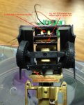
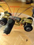
Steering is with a stepper motor, produced as a sample for me by a company called Minbea. It is not Swiss, but Japanese :). The motor is about 3.5mm in diameter and 6mm body length. The threaded spindle is another 6mm. Some of the steering assembly can be seen in the picture below.


Good luck,

Edmunds
 

Attachments

edmunds

Senior Member
Dear all,

I figured out the code from Alan and @hippy, applied it and it works like a charm.
@Ibenson - of course, there was a problem with initialisation of pixel_data.

The code is now as sleek as it can be for the part of reading where the line is and finding the position of it. The only remaining ways of improving those parts are reducing the number of pixels to look at and drop the idea of having to work out the centre of the line, but being happy with a single edge. Both offer some speed gain at the cost of lost accuracy and having to know the width of the line. Calibration procedure can be improved, but it does not have to be solved right away.

Due to the lookup table, the file is still too big to post directly, but the file is attached below.

I don't have the test track with me here, but finding the line and issuing correct steering commands now seems to work very nicely and without any hiccups in varying light conditions. I have a suspicion the steering response is too slow, however. If I cannot get the steering stepper motor to spin faster then I have a problem. This is for testing next year :).

Happy New Year to all,

Edmunds
 

Attachments

Last edited:

lbenson

Senior Member
You could still approximate the center of the line with the bit-counting method without storing any bit values. Note with which byte you first found an edge of the line, then note when you stopped seeing the line (other edge--0 bits counted or perhaps less than 5); stop the scanning process: center byte is (byte number of first edge + byte number of other edge) / 2.
 

AllyCat

Senior Member
Hi,

Well, I have a good contact with FAE in AMS, so I can ask about the above if you help formulate the question and if it is of that much interest.
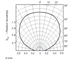
Well, almost every LED and Photosensor has its "beam width" specified in its data sheet, but not apparently the individual photodiodes in the AMS chip. Typically the beam width is defined* as the angle from "straight ahead" to where the light output or sensitivity has fallen to a half of the "straight ahead" value. It might be anything from a few degrees (or much less for a laser) up to typically 60 degrees for a "flat plate collector", which has a "Cosine response" (60 degrees has a Cosine of 1/2). Generally, if a LED/sensor claims to be very bright/sensitive then look in its data sheet to see if the beam width is very small (i.e. its high brghtness/sensitivity occurs only "straight in front"). ;)

Quite a lot of (through-hole) LEDs and Photosensors (in 3mm or 5mm packages) have a moderately narrow beam, because the curved end acts like a lens. However, the BPW34 (available in through-hole, SMD and clear/IR filter versions) is quite close to a flat plate collector, so has a wide beam width as shown below. Actually an exact cosine response (the beam-width appears as a perfect circle) is very difficult to achieve at large angles to the "ahead" axis. At the surface of the "window" (where there is a change in refractive index) some light is reflected (i.e. it never enters the material) and the rest is refracted (i.e. changes direction, as appears when looking at a stick entering water).

BPW34-BeamWidth.png

It seems that the TSL1401 is "usually" used with a lens or pinhole, which implies that it must have a wide beam width (because otherwise the pixels at the end of the sensor wouldn't see light coming through the lens/pinhole). But that means that without a lens/pinhole, a pixel located say 60 degrees from the edge of the "line" will still see half as much light as if it were directly in front. Thus the analogue output from the TSL1401 would not change sharply at the edge of the line (or anywhere else). But a digital input could, because it must switch at some threshold level.

You now appear to be getting good and usable results, but if I have understood the data sheet correctly then it seems that the output can be only a gradually-changing analogue value. So if I were using it in my proposed "car" (where the PICaxe may need almost all of its time to drive the stepper motors) then one could drive the readout clock in the "background" at high frequency using a PWM output and then just grab occasional analogue samples on-the-fly.

However, to summarise my/our question to AMS: "What is the optical beam width of the individual Photodiode sensors in the TSL1401".

Cheers, Alan.

*EDIT: With hindsight, perhaps what I have described above is better termed the half-power angle. The beam width might be considered as the angle between half-power points. i.e. double the angle.
 
Last edited:

edmunds

Senior Member
You now appear to be getting good and usable results, but if I have understood the data sheet correctly then it seems that the output can be only a gradually-changing analogue value. So if I were using it in my proposed "car" (where the PICaxe may need almost all of its time to drive the stepper motors) then one could drive the readout clock in the "background" at high frequency using a PWM output and then just grab occasional analogue samples on-the-fly.
Dear Alan,

I am calibrating the sensor with reading all analog pixel voltages, adding them up and then dividing with 128 (I could do fewer pixels, I guess). The number I get then goes into the equation to calculate a delay which essentially sets the exposure time that, in turn, affects voltage that can be taken off photodiode capacitors. This shifts all the signals towards or away from high threshold of the digital input. So in a sense, I'm using analog input, but instead of analog value that I would have to do math on, I have digital value that already means a line or not. On top of that, I do not have to calibrate on every loop, I can do it every 20 loops i.e. every second or so.

If it would actually be more efficient to read selected analog values, I have not tried, but intuitively I doubt it. Mainly, because ambient light level would still have to be judged to decide what exposure time to use, so I cannot see how the two steps could be merged.


Thank you for your input,

Edmunds
 

hippy

Technical Support
Staff member
If you roughly know how many pixels make up a line you can simply read with some contrast value, then determine if contrast were too low or too high based on the number of pixels seen for the line. If far too many or far too few, adjust and repeat, otherwise adjust but use the data.

There probably will be some adjustment period when the sensor is first put over a line but after that there should be far fewer and it auto-calibrates every sample.

I think you may be getting bogged-down and over-focused on the line detection algorithm. You have had a number of solutions which seem to have worked so it's not clear that any problems rest with line sampling itself.

Perhaps the problem is that it's not easy to tell when the algorithm is working so you are having to use the behaviour of the whole to assess things but just because it doesn't perform well doesn't mean it's the line sensing which is at fault.

You could have your PICAXE read the TSL sensor, and produce an 8-bit parallel output which shows which of 8 segments the line is in using a LED on each output. Those LED's only need a single resistor because only one will ever be set at a time so the hardware should not be too hard to add. You could also feed those 8 lines to a second PICAXE which controls the motor if you were to use a two PICAXE solution.
 

Buzby

Senior Member
... I think you may be getting bogged-down and over-focused on the line detection algorithm. ... You could have your PICAXE read the TSL sensor, and produce an 8-bit parallel output which shows which of 8 segments the line is in using a LED on each output.
I too believe that there is more than one issue here, maybe in the optical side, or the algorithm, or the mechanics.

Hippy's idea of a continuous monitor of what the TLS is seeing I think would put to bed one issue. You could even use a PCB scope with built-in OLED mounted on the car to show the analogue signal as sent from the TLS on one trace, with the second trace showing the determined on/off state from a pin on the PICAXE. Or better still, TX the values via wireless and log to Excel. This way you can repeat the same route many times, and check that the logged results are the same each time. ( In fact, the wireless idea would also let you record the steering output, which would be even more useful. )

I think you need to be absolutely certain how the TLS is behaving in the 'real world' before moving on to coding an algorithm.

Cheers,

Buzby
 

AllyCat

Senior Member
Hi,

reading all analog pixel voltages, adding them up and then dividing with 128 (I could do fewer pixels, I guess).
Yes indeed, particularly if the focus is as "soft" as I suspect. Without true "imaging" optics (a lens or pinhole), adjacent pixels will have very similar analogue values (because they "see" about the same). So, reading every 8th or 16th pixel is probably good enough. Also, note that if the line is 2 mm wide with an analogue value of (say) 100 and the background is zero, then the "average" over an 8mm "field of view" will be 25. But the optimum threshold level is probably 50. Perhaps Max + Min / 2 would be better (but is no easier to calculate).

Also, I have to agree with the previous two posts - measure what the PICaxe is actuallly doing, there are various tools immediately available such as SERTXD and DEBUG. Certainly your very small hardware size makes matters more difficult but there are various possibilities: Transmit the "diagnostics" data bytes by radio (the present favourite appears to be an HC-12), via an IR LED, or even just flash your "line illumination" LEDs.

Cheers, Alan.
 

edmunds

Senior Member
Also, I have to agree with the previous two posts - measure what the PICaxe is actuallly doing, there are various tools immediately available such as SERTXD and DEBUG. Certainly your very small hardware size makes matters more difficult but there are various possibilities: Transmit the "diagnostics" data bytes by radio (the present favourite appears to be an HC-12), via an IR LED, or even just flash your "line illumination" LEDs.
Thanks, guys. I'm pretty confident in the line reading now. There is a bluetooth SoC sitting with the other Picaxe (that is actually running the main motor), but I'm yet to get that operational. I actually have two 433MHz modules here that I got to work successfully recently. These would be small enough to stick onto the car. There is a possibility of, say 2m tiny wires to axe[whatever] cable for sertxd. Could do that, but I'm not sure that is strictly necessary. I cannot fail the line finding by manually moving the car over a sample grey surface with white line on it. I think the problem is steering response, not understanding the line position. Posting another thread with a video in a minute.


Thank you for your assistance,

Edmunds
 

edmunds

Senior Member
If you roughly know how many pixels make up a line you can simply read with some contrast value, then determine if contrast were too low or too high based on the number of pixels seen for the line. If far too many or far too few, adjust and repeat, otherwise adjust but use the data.

There probably will be some adjustment period when the sensor is first put over a line but after that there should be far fewer and it auto-calibrates every sample..
I was toying with this idea and maybe I should do more of that, but what put me off is I would like the car to stop if it looses the line, so it does not roll of the layout. Also, recognising all white for a short time i.e. perpendicular line could be valuable. I could count the perpendicular lines for various automated actions like changing speed, braking distance and similar.

Now when I think of it, maybe there is a way to do what you are suggesting only when there is some sign of line and do 'emergency stop' when there is no line at all. But then again, my lookup table needs to become more advanced. Anyway, to the previous point, this is possibly a valid and reasonable improvement point, but it works well enough as it is for now.


Thank you for your input,

Edmunds
 
Top